Showing posts with label to. Show all posts
Showing posts with label to. Show all posts
Thursday, September 26, 2013
4 Bit Analogue to Digital Converter
The operation of the converter is based on the weighted adding and transferring of the analogue input levels and the digital output levels. It consists of comparators and resistors. In theory, the number of bits is unlimited, but each bit needs a comparator and several coupling resistors. The diagram shows a 4-bit version. The value of the resistors must meet the following criteria:
 If the value of the resistors is not too low, the use of inverters with an FET (field-effect transistor) input leads to a near-ideal situation. In the present converter, complementary metal-oxide semiconductor (CMOS) inverters are used, which, in spite of their low gain, give a reasonably good performance. If standard comparators are used, take into account the output voltage range and make sure that the potential at their non-inverting inputs is set to half the supply voltage. If high accuracy is a must, comparators Type TLC3074 or similar should be used.
This type has a totem-pole output. The non-inverting inputs should be interlinked and connected to the tap of a a divider consisting of two 10 kΩ resistors across the supply lines. It is essential that the converter is driven by a low-resistance source. If necessary, this can be arranged via a suitable op amp input buffer. The converter draws a current not exceeding 5 mA.
Read More..
- R1:R2 = 1:2;
- R3:R4:R5 = 1:2:4;
- R6:R7:R8:R9 = 1:2:4:8.
 If the value of the resistors is not too low, the use of inverters with an FET (field-effect transistor) input leads to a near-ideal situation. In the present converter, complementary metal-oxide semiconductor (CMOS) inverters are used, which, in spite of their low gain, give a reasonably good performance. If standard comparators are used, take into account the output voltage range and make sure that the potential at their non-inverting inputs is set to half the supply voltage. If high accuracy is a must, comparators Type TLC3074 or similar should be used.
This type has a totem-pole output. The non-inverting inputs should be interlinked and connected to the tap of a a divider consisting of two 10 kΩ resistors across the supply lines. It is essential that the converter is driven by a low-resistance source. If necessary, this can be arranged via a suitable op amp input buffer. The converter draws a current not exceeding 5 mA.

Friday, July 12, 2013
Build a LT3582 12 DC 5V to 12V DC Converter
Using LT3582-12 dual channel DC DC converter integrated circuit, manufactured by Linear Technology, can be designed a very simple step up dc converter. This 5 to 12V c converter electronic project provide both positive and negative outputs required in many biasing applications such as active matrix OLED (organic light-emitting diode)displays as well as CCD (charge coupled device) applications.
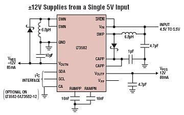
The LT3582 offer an I2C interface that can dynamically program output voltages, power sequencing and output voltage ramps as the application requires. The LT3582’s positive output voltage can be set between 3.2V and 12.775 in 25mV steps, whereas the negative output can be set between -1.2V and -13.95V in 50mV steps. The LT3582-12 is preconfigured with ±12V output, requiring no future programming.
Wednesday, July 3, 2013
Auto Changeover from Generator to Mains Supply
Because of energy crisis Load shedding may be a common problem in several countries.. Sudden power fluctuations, surge and high voltage may spoil sophisticated household appliances like TV, VCR, VCP and music system. This circuit provides protection against these problems and automatically changes the power supply from Generator output to mains supply and also switches off the generator.
Circuit descriptions
This circuit is self explanatory. When lines supply voltage crosses the preset level, Zener diode ZD4 break down and thus transistor T2 conducts, T3 does not conduct, causing the relay to de-energise. Voltage surge at the time of power resumption is protected by the delay circuit around transistor T1.
All the portable petrol and kerosene generators have a connection from CDI. To stop the engine of the generator-set, this connection is to be grounded momentarily (through the switch). This lead is to be connected with the ground through the N/C point of the relay.
Auto Changeover from Generator to Mains Supply Circuit Diagram

Instead of the one transformer, two transformers are used in series to ensure better life of the unit. Value of capacitor C2 can be increased or decreased for the variation of delay time. A negative feedback resistance, R6 (15 K-ohm to 100 k-ohm) can be incorporated between transistor T3 and T4 to overcome the damage that could be caused by voltage fluctuations.
Parts List:
Resistors (all ¼-watt, ± 5% Carbon)
R1 = 10 Ω
R2 = 1 KΩ
R3 = 820 Ω
R4 = 57 KΩ
R5 = 47 Ω
R6 = (15 KΩ to 100 KΩ)
Capacitors
C1 = 100 µF/25V
C2 = 1000 µF/12V
C3 = 100 µF/18V
Semiconductors
T1 = BC147
T2, T3 = SL100
D1, D2 = 1N4001
D3 = 1N4007
ZD1 = 5.6V/400mW
ZD2 = 7.8V/400mW
Miscellaneous
X1, X2 = 230V AC primary to 12 V, 500mA secondary transformers
RL1 = 12V/450 Ω relay
Circuit descriptions
This circuit is self explanatory. When lines supply voltage crosses the preset level, Zener diode ZD4 break down and thus transistor T2 conducts, T3 does not conduct, causing the relay to de-energise. Voltage surge at the time of power resumption is protected by the delay circuit around transistor T1.
All the portable petrol and kerosene generators have a connection from CDI. To stop the engine of the generator-set, this connection is to be grounded momentarily (through the switch). This lead is to be connected with the ground through the N/C point of the relay.
Auto Changeover from Generator to Mains Supply Circuit Diagram
Instead of the one transformer, two transformers are used in series to ensure better life of the unit. Value of capacitor C2 can be increased or decreased for the variation of delay time. A negative feedback resistance, R6 (15 K-ohm to 100 k-ohm) can be incorporated between transistor T3 and T4 to overcome the damage that could be caused by voltage fluctuations.
Parts List:
Resistors (all ¼-watt, ± 5% Carbon)
R1 = 10 Ω
R2 = 1 KΩ
R3 = 820 Ω
R4 = 57 KΩ
R5 = 47 Ω
R6 = (15 KΩ to 100 KΩ)
Capacitors
C1 = 100 µF/25V
C2 = 1000 µF/12V
C3 = 100 µF/18V
Semiconductors
T1 = BC147
T2, T3 = SL100
D1, D2 = 1N4001
D3 = 1N4007
ZD1 = 5.6V/400mW
ZD2 = 7.8V/400mW
Miscellaneous
X1, X2 = 230V AC primary to 12 V, 500mA secondary transformers
RL1 = 12V/450 Ω relay
Wednesday, June 12, 2013
The Upcoming Iphone Car Kit A Good Travel Partner To Drive
The standby capacity deficiencies and not charge in the car When you are enjoying the beauty of nature, is not bothering you by this embarrassment? You can not enjoy your favorite music on the road; When you are speeding on the highway, you can answer a important phone. Do you have encountered? Now the good new is coming.
The recent series against the iPhone and the iPod launched Six-vehicle equipment - aiPower CA601. Adjustable elastic support products, which support 90-degree rotation, to provide users with a variety of operation, standard USB output interface can not only charge for a variety of digital devices, car audio system can also realize the iPhone hands-free calls, the other , aiPower CA601 can also be iPhone and the iPods music through the FM transmitter to car stereo channels to play.
Many MP3 users to buy the car kit in order to enjoy music anytime, anywhere to bring the fun, aiPower CA601 taking into account the MP3 car kit, users can iPhone and iPod products within the audio file through the FM transmitter to car stereo playback channels This feature is not only practical, but also to restore the high-quality sound, giving the user unprecedented comfort.
And other commercial car kit is different, aiPower CA601 can adjust the angle of the stent, the fixed phone can support one end of the bracket rotated 90 degrees to meet the habits of different users, while for most users get used to the current iPhone Case issues, the Patriots designers have done in research and development CA601 sufficient time to consider the design of the stent, aiPower CA601 using a flexible design that allows the iPhone to any equipment, protective cover products easily into the holder, and ensure stable and firm.
I believe this aiPower CA601 will be your best travel companion.
Read More..
The recent series against the iPhone and the iPod launched Six-vehicle equipment - aiPower CA601. Adjustable elastic support products, which support 90-degree rotation, to provide users with a variety of operation, standard USB output interface can not only charge for a variety of digital devices, car audio system can also realize the iPhone hands-free calls, the other , aiPower CA601 can also be iPhone and the iPods music through the FM transmitter to car stereo channels to play.
Many MP3 users to buy the car kit in order to enjoy music anytime, anywhere to bring the fun, aiPower CA601 taking into account the MP3 car kit, users can iPhone and iPod products within the audio file through the FM transmitter to car stereo playback channels This feature is not only practical, but also to restore the high-quality sound, giving the user unprecedented comfort.
And other commercial car kit is different, aiPower CA601 can adjust the angle of the stent, the fixed phone can support one end of the bracket rotated 90 degrees to meet the habits of different users, while for most users get used to the current iPhone Case issues, the Patriots designers have done in research and development CA601 sufficient time to consider the design of the stent, aiPower CA601 using a flexible design that allows the iPhone to any equipment, protective cover products easily into the holder, and ensure stable and firm.
I believe this aiPower CA601 will be your best travel companion.
Tuesday, May 14, 2013
Whistle to beep circuit

This simple circuit produces a beeping sound that lasts for around 3 seconds whenever you make a whistle. The CMOS Hex inverter CD4049 is the heart of this circuit. Out of the six inverters in CD4049, U1a is wired as an audio amplifier which amplifies the signal picked up by the microphone M1.The U1b is wired as a band pass filter with center frequency around 2KHz.The filter is necessary in order to pass the frequency corresponding to whistling sound and suppress all other frequencies .If the filter is not there, the circuit could easily get false triggered.U1d is wired as a 3S delay monostable multivibrator.The output U1d drives the astable multivibrator formed by U1e and U1f.The astable multivibrator is operating around 4Hz.The combined effect is a intermittent beeping sound that lasts for around 3S.Transistor Q1 is used to drive the buzzer B1.Notes.
* Assemble the circuit on a good quality PCB.
* The circuit can be powered from a 3V battery.
* IC U1 is a CMOS CD4049 Hex inverter.
* M1 can be an electret microphone.
* B1 can be a 3V piezo buzzer.
* Mount the IC on a holder.
* The duration of beeping can be adjusted by varying the components C4 and R9.
Tuesday, April 9, 2013
Sequential Turn Lights Driver Four LED left and right sequence Particularly suited to motorcycles

Parts:
R1_____________500K  1/2W Trimmer Cermet or Carbon
R2______________47K  1/4W Resistor
R3,R4____________1K  1/4W Resistors
R5,R6,R7,R8_____10K  1/4W Resistors

C1_______________1µF  63V Polyester or electrolytic capacitor
C2_____________220µF  25V Electrolytic capacitor

D1-D8__________LEDs Yellow ultra-bright types

Q1,Q2,Q3,Q4___BC337   45V 800mA NPN Transistors

IC1____________7555 or TS555CN or TLC555CP CMos Timer IC
IC2____________4017 Decade counter with 10 decoded outputs IC

SW1____________Vehicle Turn Lights switch (See Comments)

Battery_________12V Vehicle battery
Comments:
Thisdevice was designed on request and allows sequential operation of
four Leds either to left or right direction, obtained by means of a
7555 CMos timer IC (IC1) wired as an astable multivibrator driving a
Decade counter (IC2). This IC is set to count a sequence of four by
connection of pin #10 to pin #15, but any sequence count in the 2-10
range can be set by choosing the appropriate pin connection. Obviously,
LEDs, Transistors and their respective Base-limiting resistors must
also be added or omitted accordingly.
R1 is a variable resistor
(Trimmer), used to set the desired speed of the LEDs. SW1 is a
change-over switch that should already exist in your motorcycle,
having a center-off position and Turn-left and Turn-right positions.
D1, D3, D5 and D7 are the Turn-left LEDs; D2, D4, D6 and D8 are the Turn-right LEDs.
For a motorcycle they are arranged on a single board about 20 - 25 cm
wide as shown in the image below. The outer red LEDs are the
tail/brake lights and can be driven by a circuit like the LED driven
tail/brake Light Cluster available on this website.

Note:
- The use of high brightness, high efficiency yellow LED types of suitable size is mandatory.
Friday, March 29, 2013
How to Generate Pure Oxygen and Hydrogen at Home
We all know the potentials of these two gases and how important they are on this planet. Oxygen is the life sustaining gas without which no living creature on this planet can live, hydrogen on other hand has its own merits and can be considered as the future fuel which would ultimately power our vehicles and cook our foods once all the naturally available fossil resources goes out of stock and gets depleted.
In school days we all have learned and witnessed the process called the electrolysis of water, where water which is made up of two main constituents H2O (two parts hydrogen and one part oxygen) is broken down forcibly with the help of electric current.
However in this process, normally a pinch of salt is added or sometime a drop of sulfuric acid is added for enhancing the electrolysis process.
This results in speedy electrolysis process, and we are able to see large and thick amounts of gas bubbles come out across the two electrodes which are connected to a potential difference source or simply to a battery.
However theres an misconception that the above process generates oxygen and hydrogen with ease, in fact that may not be the case and if carefully assess the process yo will find its not the water but the added chemical which is getting broken in the influence of the electric current.
That means if we add salt to water, the electrolysis process will generate the gas chlorine and sodium deposits over the two electrodes and not oxygen or hydrogen.....you can expect the generation of H and O, but in very negligible volumes.
For generating pure oxygen and hydrogen through the process of breaking down water components we need to implement the process of electrolysis without the addition of any foreign chemical into water.
In simple words the procedure must be carried out breaking H2O directly without the help of any catalyst medium.
However if you try to do this, you will find the process to be very lethargic and absolutely impossible, because the bond between the H2O components are so great, it might become impossible to disintegrate them into parts.
But it can be done through brute force, means instead of using low power DC, if we use mains AC, and introduce it into a container filled with water, we might just be able to force the liquid to separate into its pure forms.
THIS METHOD HAS BEEN DISCOVERED BY ME, I ASSUME SO, BECAUSE ITS NOT BEEN DISCUSSED ANYWHERE ELSE ON THE NET SO FAR.
OK, the method is as simple as it can be, while experimenting I found that by converting mains AC to DC, the process aggravates more rapidly and thick fogs of gases can be seen across the respective electrodes.
And it is definitely important to use DC. otherwise the gases will alternately produced over the two electrodes haphazardly completely ruining the results.
So....its all about making a bridge rectifier circuit using four diodes, 1n4007 will do. take four of them and construct the bridge rectifier module and next wire up the system as per the shown diagram.
The glass apparatus will need to be carefully set. As can be see in the figure, the two glass tubes are inverted inside a container filled with water.
The two tubes should be filled with the water such that both the tubes share the container water among themselves.
A couple of copper electrodes are fitted in such a way that they get inside the tubes water content just as shown in the figure.
The electrodes are terminated out through respective wires connections which are further connected to the bridge rectifiers positive and negative outputs.
The bridge rectifier inputs are in turn connected to mains AC.
The moment power is switched ON, thick surfs of bubbles can be seen coming out from the electrodes and exploding into the respective gas forms into the vacant area of the tubes.
Since theres no external chemical involved here, we can assume the gas formed and collected inside the tubes to be pure oxygen and hydrogen.
As the process is allowed to continue, you will find the water level coming down and getting transformed into oxygen and hydrogen within the two tubes.
The tubes should have a valve type arrangement at their top termination, so that the accumulated gas can be either transferred to a larger container or directly accessed from the nozzles by releasing the taps or the valve mechanism.
THE WHOLE SYSTEM INVOLVES HIGH AC AND DC POTENTIALS, DEATH CAN COME WITHIN MINUTES IF ANY OF THE PART OF THE SYSTEM IS TOUCHED, EVEN THE WATER IS HIGHLY DANGEROUS TO TOUCH IN SWITCHED ON POSITION. DO NOT SHORT CIRCUIT THE ELECTRODES, WHICH MAY RESULT IN FIRE AND HUGE EXPLOSIONS. GREAT CAUTION MUST EXERCISED WHILE HANDLING THIS SET UP.

How to construct the bridge rectifier and wire it for the above apparatus:

In school days we all have learned and witnessed the process called the electrolysis of water, where water which is made up of two main constituents H2O (two parts hydrogen and one part oxygen) is broken down forcibly with the help of electric current.
However in this process, normally a pinch of salt is added or sometime a drop of sulfuric acid is added for enhancing the electrolysis process.
This results in speedy electrolysis process, and we are able to see large and thick amounts of gas bubbles come out across the two electrodes which are connected to a potential difference source or simply to a battery.
However theres an misconception that the above process generates oxygen and hydrogen with ease, in fact that may not be the case and if carefully assess the process yo will find its not the water but the added chemical which is getting broken in the influence of the electric current.
That means if we add salt to water, the electrolysis process will generate the gas chlorine and sodium deposits over the two electrodes and not oxygen or hydrogen.....you can expect the generation of H and O, but in very negligible volumes.
For generating pure oxygen and hydrogen through the process of breaking down water components we need to implement the process of electrolysis without the addition of any foreign chemical into water.
In simple words the procedure must be carried out breaking H2O directly without the help of any catalyst medium.
However if you try to do this, you will find the process to be very lethargic and absolutely impossible, because the bond between the H2O components are so great, it might become impossible to disintegrate them into parts.
But it can be done through brute force, means instead of using low power DC, if we use mains AC, and introduce it into a container filled with water, we might just be able to force the liquid to separate into its pure forms.
THIS METHOD HAS BEEN DISCOVERED BY ME, I ASSUME SO, BECAUSE ITS NOT BEEN DISCUSSED ANYWHERE ELSE ON THE NET SO FAR.
OK, the method is as simple as it can be, while experimenting I found that by converting mains AC to DC, the process aggravates more rapidly and thick fogs of gases can be seen across the respective electrodes.
And it is definitely important to use DC. otherwise the gases will alternately produced over the two electrodes haphazardly completely ruining the results.
So....its all about making a bridge rectifier circuit using four diodes, 1n4007 will do. take four of them and construct the bridge rectifier module and next wire up the system as per the shown diagram.
The glass apparatus will need to be carefully set. As can be see in the figure, the two glass tubes are inverted inside a container filled with water.
The two tubes should be filled with the water such that both the tubes share the container water among themselves.
A couple of copper electrodes are fitted in such a way that they get inside the tubes water content just as shown in the figure.
The electrodes are terminated out through respective wires connections which are further connected to the bridge rectifiers positive and negative outputs.
The bridge rectifier inputs are in turn connected to mains AC.
The moment power is switched ON, thick surfs of bubbles can be seen coming out from the electrodes and exploding into the respective gas forms into the vacant area of the tubes.
Since theres no external chemical involved here, we can assume the gas formed and collected inside the tubes to be pure oxygen and hydrogen.
As the process is allowed to continue, you will find the water level coming down and getting transformed into oxygen and hydrogen within the two tubes.
The tubes should have a valve type arrangement at their top termination, so that the accumulated gas can be either transferred to a larger container or directly accessed from the nozzles by releasing the taps or the valve mechanism.
THE WHOLE SYSTEM INVOLVES HIGH AC AND DC POTENTIALS, DEATH CAN COME WITHIN MINUTES IF ANY OF THE PART OF THE SYSTEM IS TOUCHED, EVEN THE WATER IS HIGHLY DANGEROUS TO TOUCH IN SWITCHED ON POSITION. DO NOT SHORT CIRCUIT THE ELECTRODES, WHICH MAY RESULT IN FIRE AND HUGE EXPLOSIONS. GREAT CAUTION MUST EXERCISED WHILE HANDLING THIS SET UP.
How to construct the bridge rectifier and wire it for the above apparatus:
Monday, March 25, 2013
Static 0 to 9 display
Description.
The circuit shown here is of a simple 0 to 9 display that can be employed in a lot of applications. The circuit is based on asynchronous decade counter 7490(IC2), a 7 segment display (D1), and a seven segment decoder/driver IC 7446 (IC1).
The seven segment display consists of 7 LEDs labelled ‘a’ through ‘g’. By forward biasing different LEDs, we can display the digits 0 through 9. Seven segment displays are of two types, common cathode and common anode. In common anode type anodes of all the seven LEDs are tied together, while in common cathode type all cathodes are tied together. The seven segment display used here is a common anode type .Resistor R1 to R7 are current limiting resistors. IC 7446 is a decoder/driver IC used to drive the seven segment display.
Working of this circuit is very simple. For every clock pulse the BCD output of the IC2 (7490) will advance by one bit. The IC1 (7446) will decode this BCD output to corresponding the seven segment form and will drive the display to indicate the corresponding digit.
Circuit diagram.

Read More..
The circuit shown here is of a simple 0 to 9 display that can be employed in a lot of applications. The circuit is based on asynchronous decade counter 7490(IC2), a 7 segment display (D1), and a seven segment decoder/driver IC 7446 (IC1).
The seven segment display consists of 7 LEDs labelled ‘a’ through ‘g’. By forward biasing different LEDs, we can display the digits 0 through 9. Seven segment displays are of two types, common cathode and common anode. In common anode type anodes of all the seven LEDs are tied together, while in common cathode type all cathodes are tied together. The seven segment display used here is a common anode type .Resistor R1 to R7 are current limiting resistors. IC 7446 is a decoder/driver IC used to drive the seven segment display.
Working of this circuit is very simple. For every clock pulse the BCD output of the IC2 (7490) will advance by one bit. The IC1 (7446) will decode this BCD output to corresponding the seven segment form and will drive the display to indicate the corresponding digit.
Circuit diagram.
Notes.
§ The circuit can be assembled on a perf board.
§ Use 5V DC for powering the circuit.
§ The clock can be given to the pin 14 of IC2.
§ D1 must be a seven segment common anode display.
§ All ICs must be mounted on holders.
Subscribe to:
Posts (Atom)