Showing posts with label and. Show all posts
Showing posts with label and. Show all posts
Monday, July 29, 2013
2008 Mercury Sable Passenger Compartment Fuse Panel and Relay Code Diagram
If you found electrical components are not working in a vehicle, a fuse may have blown, so check the appropriate fuses before replacing any electrical component. You can identify the blown fuse by the broken wire within the fuse. The following schematic / diagram shows the location of The 2008 Mercury Sable Passenger Compartment Fuse Panel and Relay. The fuse panel and relay of the 2008 Mercury Sable are located under the instrument panel to the left of the steering wheel.

Always replace the fuse with one that has the specified rating, if the amperage ratings of the replacing fuse is higher, A fuse with higher amperage rating can cause severe wire damage and could start a fire. The table below shows you the exact amperage rating, location and code for each fuse and relay. (fuse number, amperage rating, and circuit protected).
2008 Mercury Sable Passenger Compartment Fuse Panel and Relay Code:
Fuse | Amperage | Description of Circuit Protected |
| 1 2 | 30A 15A | Smart window motor Brake on/off switch, High-mounted brake lamp |
3 | 15A | SDARS, Bluetooth, Family entertainment system (FES)/Rear seat control |
| 4 5 6 7 8 9 10 11 12 13 14 15 16 17 18 19 20 21 22 23 24 25 26 27 28 29 30 31 32 33 34 | 30A 10A 20A 10A 10A 15A 15A 10A 7.5A 5A 10A 10A 15A 20A 20A 25A 15A 15A 15A 15A 20A 10A 10A 20A 5A 5A 5A 10A 10A 10A 5A | Spare SPDJB logic power Turn signals Low beam headlamps (left) Low beam headlamps (right) Interior lights, Cargo lamps Backlighting, Puddle lamps All wheel drive Memory seat/mirror switches, Memory module FEPS module Analog clock Climate control Spare All power lock motor feeds, Decklid release Spare Moon roof OBDII connector Fog lamps Park lamps, License lamps High beam headlamps Horn relay Demand lamps/Interior lamps Instrument panel cluster Adjustable pedal switch Radio, Radio start signal Instrument panel cluster Overdrive cancel switch Compass, Automatic dimming rear view mirror Restraint control module Spare AWD module |
35 | 10A | Steering rotation sensor, FEPS, Rear park assist, Heated seat modules |
| 36 37 38 39 40 41 42 43 44 | 5A 10A 20A 20A 20A 15A 10A 10A 10A | PATS module Climate control Subwoofer (Audiophile radio) Radio Spare Mic mirror, Moon roof, Front lock switches, Radio Spare Spare Spare |
45 | 5A | Relay coils: PDB, Auxiliary A/C, Front and rear wipers, Front blower motor |
46 | 7.5A | Occupant Classification Sensor (OCS), Passenger Airbag Deactivation Indicator (PADI) |
| 47 48 | 30A CB* - | Power windows Delayed accessory relay |
* CB: Circuit Breaker

Thursday, July 11, 2013
Digital Clock with Timer and Solar Panel Regulator
This is a combination digital clock timer and solar panel charge controller used to maintain a deep cycle battery from a solar panel. The timer output is used to control a 12 volt load for a 32 minute time interval each day. Start time is set using 9 dip switches and ends 32 minutes later. The 32 minute duration is set by selecting the 5th bit (2^5 = 32) of a 4040 binary counter (pin 2). The timer also has a manual toggle switch so the load can be manually switched on or off and automatically shuts off after 32 minutes. The time duration can be longer or shorter (8,16,32,64,128,256 minutes etc.) by selecting the appropriate bit of the counter. The timer circuit is shown in the lower schematic just above the regulator.
Basic Clock Circuit diagram
The basic clock circuit (top schematic below) is similar to the binary clock (on another page) and uses 7 ICs to produce the 20 digital bits for 12 hour time, plus AM and PM. A standard watch crystal oscillator (32,768) is used as the time base and is divided down to 1/2 half second by the 4020 binary counter. One half of a 4013 data latch is used to divide the 1/2 second signal by 2 and produce a one second pulse that drives the seconds counter (74HC390 colored purple). The minutes are advanced by decoding 60 seconds (40 + 20) and then resetting the seconds counter to 0 and at the same time advancing the minutes counter. The same procedure is used to advance the hours. The second half of the 4013 latch is used to indicate AM or PM and is toggled by decoding 13 hours and resetting the hours to 0 and then advancing the hours to "one".
Clock Display Circuit diagram
The clock display circuit is shown in the second drawing below and uses 6 more ICs to decode the binary data and drive four seven segment LED displays. The 10s of hours digit is driven with a single 3904 transistor. Two multiplexer circuits (4053) are used to manually select either minutes or seconds for the right two display digits. The two switches shown between the 4053s and below the left 4053 are both part of one DPDT switch which selects either seconds or minutes for the 1X and 10X digits. This switch is shown in the seconds position and the hours digits are blanked with a low signal on pin 4 of the 4511.
The display can also be toggled on and off (totally blank) using a set/reset latch made from a couple 74HC00 NAND gates. A momentary DPDT switch is used to control the latch and toggle the display on or off. The second pole of this switch is used on the upper drawing (connected to the run/stop switch) to set the hours and minutes. Thus this same switch performs both functions of blanking the display and setting the time. The run/stop switch is shown in the normal running mode and supplies a low signal to a NAND gate which prevents accidental setting the time while the clock is running.
Clock Timer Circuit diagram
The run/stop switch also turns on the display (through the diode D2) when in the stop position. The procedure for setting the clock would be to set the (run/stop) switch the stop position and the (seconds/minutes) switch to the minutes position. Then toggle the momentary switch to set minutes and hours of the current time plus one minute. The clock can then be started with the run/stop switch at precisely the right time (+/- 0.5 seconds).
Voltage Regulator (13.6 volts)
The voltage regulator in the lower drawing maintains the battery at 13.6 volts and also supplies the clock and timer circuits with 4.3 volts. The charge LED indicator only comes on when the regulator is supplying max charge to the battery. When the battery voltage reaches 13.6 the regulator reduces the current to whatever is necessary to maintain the voltage and the charge indicator will turn off. The unit I built also included a battery condition indicator (voltmeter using 4 LEDs) to indicate the battery condition so that a failure of the regulator would be indicated by the charge indicator LED turned off and less than 4 LEDs lit on the voltmeter.
Basic Clock Circuit diagram
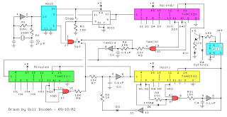 |
The basic clock circuit (top schematic below) is similar to the binary clock (on another page) and uses 7 ICs to produce the 20 digital bits for 12 hour time, plus AM and PM. A standard watch crystal oscillator (32,768) is used as the time base and is divided down to 1/2 half second by the 4020 binary counter. One half of a 4013 data latch is used to divide the 1/2 second signal by 2 and produce a one second pulse that drives the seconds counter (74HC390 colored purple). The minutes are advanced by decoding 60 seconds (40 + 20) and then resetting the seconds counter to 0 and at the same time advancing the minutes counter. The same procedure is used to advance the hours. The second half of the 4013 latch is used to indicate AM or PM and is toggled by decoding 13 hours and resetting the hours to 0 and then advancing the hours to "one".
Clock Display Circuit diagram
 |
The clock display circuit is shown in the second drawing below and uses 6 more ICs to decode the binary data and drive four seven segment LED displays. The 10s of hours digit is driven with a single 3904 transistor. Two multiplexer circuits (4053) are used to manually select either minutes or seconds for the right two display digits. The two switches shown between the 4053s and below the left 4053 are both part of one DPDT switch which selects either seconds or minutes for the 1X and 10X digits. This switch is shown in the seconds position and the hours digits are blanked with a low signal on pin 4 of the 4511.
The display can also be toggled on and off (totally blank) using a set/reset latch made from a couple 74HC00 NAND gates. A momentary DPDT switch is used to control the latch and toggle the display on or off. The second pole of this switch is used on the upper drawing (connected to the run/stop switch) to set the hours and minutes. Thus this same switch performs both functions of blanking the display and setting the time. The run/stop switch is shown in the normal running mode and supplies a low signal to a NAND gate which prevents accidental setting the time while the clock is running.
Clock Timer Circuit diagram
 |
The run/stop switch also turns on the display (through the diode D2) when in the stop position. The procedure for setting the clock would be to set the (run/stop) switch the stop position and the (seconds/minutes) switch to the minutes position. Then toggle the momentary switch to set minutes and hours of the current time plus one minute. The clock can then be started with the run/stop switch at precisely the right time (+/- 0.5 seconds).
Voltage Regulator (13.6 volts)
 |
The voltage regulator in the lower drawing maintains the battery at 13.6 volts and also supplies the clock and timer circuits with 4.3 volts. The charge LED indicator only comes on when the regulator is supplying max charge to the battery. When the battery voltage reaches 13.6 the regulator reduces the current to whatever is necessary to maintain the voltage and the charge indicator will turn off. The unit I built also included a battery condition indicator (voltmeter using 4 LEDs) to indicate the battery condition so that a failure of the regulator would be indicated by the charge indicator LED turned off and less than 4 LEDs lit on the voltmeter.
Friday, July 5, 2013
Simple SWR and PWR Meter
Many SWR / Power meter used by amateurs to the extent reasonably accurate continuous average power with a CW key-down signal, but can not reliably be used with other (modulated) signals PEP or average power measurement. These laws seek to show why the power measurement can be a sensitive issue, and because the interpretation of a yardstick of power can be a lot of attention and knowledge of construction and the characteristics of the instrument.
A reflectometer-type SWR meter can be calibrated to give power back and forth (PF, Pr) on a power supply. A classic example is the 1943 Bird Series power meter, which is a directional coupler is used to obtain a sample voltage proportional to the voltage wave or forward or backward on the feeder (VF, VR). Other systems, perhaps more suitable for HF, then use a bridge circuit to perform the same function.
Simple SWR and PWR Meter Circuit diagram

The sample voltage is then rectified and displayed on a meter that is calibrated in watts. If the counter is typically a coil, the scale, so the numbers on the scale, representing the power, are proportional to the square of the applied voltage or the current calibration. The theory of this type is very simple and is based on the concept represented by PF = Vf2/Zo. Note that if the power supply has an impedance that differs from the value of how the instrument is calibrated, there will be a mistake. The output voltage of the rectifier is a solid phase of VF or VR, and this is expected in the calibration of the meter.
Examples of directional coupling, and bridge-type reflectometers are shown in Figures 1 and 2, while the bird directional coupler means 43 is illustrated in Figure 3. Note that in all cases the measurement circuit, a combination with a small RC time constant, making the system unsuitable for the measurement of PEP, and the absence of a specific device quadratic, making them unsuitable for measuring the average power .
A reflectometer-type SWR meter can be calibrated to give power back and forth (PF, Pr) on a power supply. A classic example is the 1943 Bird Series power meter, which is a directional coupler is used to obtain a sample voltage proportional to the voltage wave or forward or backward on the feeder (VF, VR). Other systems, perhaps more suitable for HF, then use a bridge circuit to perform the same function.
Simple SWR and PWR Meter Circuit diagram
The sample voltage is then rectified and displayed on a meter that is calibrated in watts. If the counter is typically a coil, the scale, so the numbers on the scale, representing the power, are proportional to the square of the applied voltage or the current calibration. The theory of this type is very simple and is based on the concept represented by PF = Vf2/Zo. Note that if the power supply has an impedance that differs from the value of how the instrument is calibrated, there will be a mistake. The output voltage of the rectifier is a solid phase of VF or VR, and this is expected in the calibration of the meter.
Examples of directional coupling, and bridge-type reflectometers are shown in Figures 1 and 2, while the bird directional coupler means 43 is illustrated in Figure 3. Note that in all cases the measurement circuit, a combination with a small RC time constant, making the system unsuitable for the measurement of PEP, and the absence of a specific device quadratic, making them unsuitable for measuring the average power .
Wednesday, May 29, 2013

Tuesday, April 9, 2013
Sequential Turn Lights Driver Four LED left and right sequence Particularly suited to motorcycles

Parts:
R1_____________500K  1/2W Trimmer Cermet or Carbon
R2______________47K  1/4W Resistor
R3,R4____________1K  1/4W Resistors
R5,R6,R7,R8_____10K  1/4W Resistors

C1_______________1µF  63V Polyester or electrolytic capacitor
C2_____________220µF  25V Electrolytic capacitor

D1-D8__________LEDs Yellow ultra-bright types

Q1,Q2,Q3,Q4___BC337   45V 800mA NPN Transistors

IC1____________7555 or TS555CN or TLC555CP CMos Timer IC
IC2____________4017 Decade counter with 10 decoded outputs IC

SW1____________Vehicle Turn Lights switch (See Comments)

Battery_________12V Vehicle battery
Comments:
Thisdevice was designed on request and allows sequential operation of
four Leds either to left or right direction, obtained by means of a
7555 CMos timer IC (IC1) wired as an astable multivibrator driving a
Decade counter (IC2). This IC is set to count a sequence of four by
connection of pin #10 to pin #15, but any sequence count in the 2-10
range can be set by choosing the appropriate pin connection. Obviously,
LEDs, Transistors and their respective Base-limiting resistors must
also be added or omitted accordingly.
R1 is a variable resistor
(Trimmer), used to set the desired speed of the LEDs. SW1 is a
change-over switch that should already exist in your motorcycle,
having a center-off position and Turn-left and Turn-right positions.
D1, D3, D5 and D7 are the Turn-left LEDs; D2, D4, D6 and D8 are the Turn-right LEDs.
For a motorcycle they are arranged on a single board about 20 - 25 cm
wide as shown in the image below. The outer red LEDs are the
tail/brake lights and can be driven by a circuit like the LED driven
tail/brake Light Cluster available on this website.

Note:
- The use of high brightness, high efficiency yellow LED types of suitable size is mandatory.
Friday, March 29, 2013
How to Generate Pure Oxygen and Hydrogen at Home
We all know the potentials of these two gases and how important they are on this planet. Oxygen is the life sustaining gas without which no living creature on this planet can live, hydrogen on other hand has its own merits and can be considered as the future fuel which would ultimately power our vehicles and cook our foods once all the naturally available fossil resources goes out of stock and gets depleted.
In school days we all have learned and witnessed the process called the electrolysis of water, where water which is made up of two main constituents H2O (two parts hydrogen and one part oxygen) is broken down forcibly with the help of electric current.
However in this process, normally a pinch of salt is added or sometime a drop of sulfuric acid is added for enhancing the electrolysis process.
This results in speedy electrolysis process, and we are able to see large and thick amounts of gas bubbles come out across the two electrodes which are connected to a potential difference source or simply to a battery.
However theres an misconception that the above process generates oxygen and hydrogen with ease, in fact that may not be the case and if carefully assess the process yo will find its not the water but the added chemical which is getting broken in the influence of the electric current.
That means if we add salt to water, the electrolysis process will generate the gas chlorine and sodium deposits over the two electrodes and not oxygen or hydrogen.....you can expect the generation of H and O, but in very negligible volumes.
For generating pure oxygen and hydrogen through the process of breaking down water components we need to implement the process of electrolysis without the addition of any foreign chemical into water.
In simple words the procedure must be carried out breaking H2O directly without the help of any catalyst medium.
However if you try to do this, you will find the process to be very lethargic and absolutely impossible, because the bond between the H2O components are so great, it might become impossible to disintegrate them into parts.
But it can be done through brute force, means instead of using low power DC, if we use mains AC, and introduce it into a container filled with water, we might just be able to force the liquid to separate into its pure forms.
THIS METHOD HAS BEEN DISCOVERED BY ME, I ASSUME SO, BECAUSE ITS NOT BEEN DISCUSSED ANYWHERE ELSE ON THE NET SO FAR.
OK, the method is as simple as it can be, while experimenting I found that by converting mains AC to DC, the process aggravates more rapidly and thick fogs of gases can be seen across the respective electrodes.
And it is definitely important to use DC. otherwise the gases will alternately produced over the two electrodes haphazardly completely ruining the results.
So....its all about making a bridge rectifier circuit using four diodes, 1n4007 will do. take four of them and construct the bridge rectifier module and next wire up the system as per the shown diagram.
The glass apparatus will need to be carefully set. As can be see in the figure, the two glass tubes are inverted inside a container filled with water.
The two tubes should be filled with the water such that both the tubes share the container water among themselves.
A couple of copper electrodes are fitted in such a way that they get inside the tubes water content just as shown in the figure.
The electrodes are terminated out through respective wires connections which are further connected to the bridge rectifiers positive and negative outputs.
The bridge rectifier inputs are in turn connected to mains AC.
The moment power is switched ON, thick surfs of bubbles can be seen coming out from the electrodes and exploding into the respective gas forms into the vacant area of the tubes.
Since theres no external chemical involved here, we can assume the gas formed and collected inside the tubes to be pure oxygen and hydrogen.
As the process is allowed to continue, you will find the water level coming down and getting transformed into oxygen and hydrogen within the two tubes.
The tubes should have a valve type arrangement at their top termination, so that the accumulated gas can be either transferred to a larger container or directly accessed from the nozzles by releasing the taps or the valve mechanism.
THE WHOLE SYSTEM INVOLVES HIGH AC AND DC POTENTIALS, DEATH CAN COME WITHIN MINUTES IF ANY OF THE PART OF THE SYSTEM IS TOUCHED, EVEN THE WATER IS HIGHLY DANGEROUS TO TOUCH IN SWITCHED ON POSITION. DO NOT SHORT CIRCUIT THE ELECTRODES, WHICH MAY RESULT IN FIRE AND HUGE EXPLOSIONS. GREAT CAUTION MUST EXERCISED WHILE HANDLING THIS SET UP.

How to construct the bridge rectifier and wire it for the above apparatus:

In school days we all have learned and witnessed the process called the electrolysis of water, where water which is made up of two main constituents H2O (two parts hydrogen and one part oxygen) is broken down forcibly with the help of electric current.
However in this process, normally a pinch of salt is added or sometime a drop of sulfuric acid is added for enhancing the electrolysis process.
This results in speedy electrolysis process, and we are able to see large and thick amounts of gas bubbles come out across the two electrodes which are connected to a potential difference source or simply to a battery.
However theres an misconception that the above process generates oxygen and hydrogen with ease, in fact that may not be the case and if carefully assess the process yo will find its not the water but the added chemical which is getting broken in the influence of the electric current.
That means if we add salt to water, the electrolysis process will generate the gas chlorine and sodium deposits over the two electrodes and not oxygen or hydrogen.....you can expect the generation of H and O, but in very negligible volumes.
For generating pure oxygen and hydrogen through the process of breaking down water components we need to implement the process of electrolysis without the addition of any foreign chemical into water.
In simple words the procedure must be carried out breaking H2O directly without the help of any catalyst medium.
However if you try to do this, you will find the process to be very lethargic and absolutely impossible, because the bond between the H2O components are so great, it might become impossible to disintegrate them into parts.
But it can be done through brute force, means instead of using low power DC, if we use mains AC, and introduce it into a container filled with water, we might just be able to force the liquid to separate into its pure forms.
THIS METHOD HAS BEEN DISCOVERED BY ME, I ASSUME SO, BECAUSE ITS NOT BEEN DISCUSSED ANYWHERE ELSE ON THE NET SO FAR.
OK, the method is as simple as it can be, while experimenting I found that by converting mains AC to DC, the process aggravates more rapidly and thick fogs of gases can be seen across the respective electrodes.
And it is definitely important to use DC. otherwise the gases will alternately produced over the two electrodes haphazardly completely ruining the results.
So....its all about making a bridge rectifier circuit using four diodes, 1n4007 will do. take four of them and construct the bridge rectifier module and next wire up the system as per the shown diagram.
The glass apparatus will need to be carefully set. As can be see in the figure, the two glass tubes are inverted inside a container filled with water.
The two tubes should be filled with the water such that both the tubes share the container water among themselves.
A couple of copper electrodes are fitted in such a way that they get inside the tubes water content just as shown in the figure.
The electrodes are terminated out through respective wires connections which are further connected to the bridge rectifiers positive and negative outputs.
The bridge rectifier inputs are in turn connected to mains AC.
The moment power is switched ON, thick surfs of bubbles can be seen coming out from the electrodes and exploding into the respective gas forms into the vacant area of the tubes.
Since theres no external chemical involved here, we can assume the gas formed and collected inside the tubes to be pure oxygen and hydrogen.
As the process is allowed to continue, you will find the water level coming down and getting transformed into oxygen and hydrogen within the two tubes.
The tubes should have a valve type arrangement at their top termination, so that the accumulated gas can be either transferred to a larger container or directly accessed from the nozzles by releasing the taps or the valve mechanism.
THE WHOLE SYSTEM INVOLVES HIGH AC AND DC POTENTIALS, DEATH CAN COME WITHIN MINUTES IF ANY OF THE PART OF THE SYSTEM IS TOUCHED, EVEN THE WATER IS HIGHLY DANGEROUS TO TOUCH IN SWITCHED ON POSITION. DO NOT SHORT CIRCUIT THE ELECTRODES, WHICH MAY RESULT IN FIRE AND HUGE EXPLOSIONS. GREAT CAUTION MUST EXERCISED WHILE HANDLING THIS SET UP.
How to construct the bridge rectifier and wire it for the above apparatus:
Subscribe to:
Posts (Atom)