Showing posts with label converter. Show all posts
Showing posts with label converter. Show all posts
Thursday, September 26, 2013
4 Bit Analogue to Digital Converter
The operation of the converter is based on the weighted adding and transferring of the analogue input levels and the digital output levels. It consists of comparators and resistors. In theory, the number of bits is unlimited, but each bit needs a comparator and several coupling resistors. The diagram shows a 4-bit version. The value of the resistors must meet the following criteria:
 If the value of the resistors is not too low, the use of inverters with an FET (field-effect transistor) input leads to a near-ideal situation. In the present converter, complementary metal-oxide semiconductor (CMOS) inverters are used, which, in spite of their low gain, give a reasonably good performance. If standard comparators are used, take into account the output voltage range and make sure that the potential at their non-inverting inputs is set to half the supply voltage. If high accuracy is a must, comparators Type TLC3074 or similar should be used.
This type has a totem-pole output. The non-inverting inputs should be interlinked and connected to the tap of a a divider consisting of two 10 kΩ resistors across the supply lines. It is essential that the converter is driven by a low-resistance source. If necessary, this can be arranged via a suitable op amp input buffer. The converter draws a current not exceeding 5 mA.
Read More..
- R1:R2 = 1:2;
- R3:R4:R5 = 1:2:4;
- R6:R7:R8:R9 = 1:2:4:8.
 If the value of the resistors is not too low, the use of inverters with an FET (field-effect transistor) input leads to a near-ideal situation. In the present converter, complementary metal-oxide semiconductor (CMOS) inverters are used, which, in spite of their low gain, give a reasonably good performance. If standard comparators are used, take into account the output voltage range and make sure that the potential at their non-inverting inputs is set to half the supply voltage. If high accuracy is a must, comparators Type TLC3074 or similar should be used.
This type has a totem-pole output. The non-inverting inputs should be interlinked and connected to the tap of a a divider consisting of two 10 kΩ resistors across the supply lines. It is essential that the converter is driven by a low-resistance source. If necessary, this can be arranged via a suitable op amp input buffer. The converter draws a current not exceeding 5 mA.

Friday, July 12, 2013
Build a LT3582 12 DC 5V to 12V DC Converter
Using LT3582-12 dual channel DC DC converter integrated circuit, manufactured by Linear Technology, can be designed a very simple step up dc converter. This 5 to 12V c converter electronic project provide both positive and negative outputs required in many biasing applications such as active matrix OLED (organic light-emitting diode)displays as well as CCD (charge coupled device) applications.
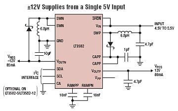
The LT3582 offer an I2C interface that can dynamically program output voltages, power sequencing and output voltage ramps as the application requires. The LT3582’s positive output voltage can be set between 3.2V and 12.775 in 25mV steps, whereas the negative output can be set between -1.2V and -13.95V in 50mV steps. The LT3582-12 is preconfigured with ±12V output, requiring no future programming.
Friday, March 29, 2013
Dual Polarity 5 Volt Converter Using LM2685
A symmetrical ±5V power supply is often needed for small, battery-operated operational amplifier projects and analogue circuits. An IC that can easily be used for this purpose is the National Semiconductor LM2685. It contains a switched-capacitor voltage doubler followed by a 5-V regulator. A voltage inverter integrated into the same IC, which also uses the switched-capacitor technique, runs from this output voltage. The external circuitry is limited to two pump capacitors and three electrolytic storage capacitors.
The IC can work with an input voltage between +2.85V and +6.5V, which makes it well suited for battery-operated equipment. The input voltage is first applied to a voltage doubler operating at 130kHz. The external capacitor for this is connected to pins 13 and 14. The output voltage of this doubler is filtered by capacitor C3, which is connected to pin 12. If the input voltage lies between +5.4 and +6.5V, the voltage doubler switches off and passes the input voltage directly through to the following +5V low-dropout regulator, which can deliver up to 50mA. C4 is used as the output filter capacitor.
 All that is necessary to generate the –5-V output voltage is to invert the +5-V voltage. This is done by a clocked power-MOS circuit that first charges capacitor C2, which is connected between pins 8 and 9, and then reverses its polarity. This chopped voltage must be filtered by C5 at the output. The unregulated –5V output can supply up to 15mA. The LM 2865 voltage converter IC also has a chip-enable input (CE) and two control inputs, SDP (shut down positive) and SDN (shut down negative). If CE is set Low, the entire IC is switched off (shut down), and its current consumption drops to typically 6µA.
The CE input can thus be used to switch the connected circuit on or off, without having to disconnect the battery. The SDP and SDN inputs can be used to switch the VPSW and VNSW outputs, respectively. These two pins are connected to the voltage outputs via two low-resistance CMOS switches. This allows the negative output to be separately switched off, whereby the voltage inverter is also switched off. Switching off with SDP not only opens the output switch but also stops the oscillator.
There is thus no longer any input voltage for the –5V inverter, so the –5V output also drops out. The SDP and SDN inputs are set Low (<0.8v)>2.4V) for switching off the associated voltage(s). The positive output of the LM 2865 is short-circuit proof. However, a short circuit between the positive and negative outputs must always be avoided. The IC is protected against thermal destruction by an over-temperature monitor. It switches off automatically at a chip temperature of around 150C. The full type number of the IC is LM2685MTC. It comes in a TSSOP14 SMD package. National Semiconductor can be found on the Internet under www.national.com.
Read More..
The IC can work with an input voltage between +2.85V and +6.5V, which makes it well suited for battery-operated equipment. The input voltage is first applied to a voltage doubler operating at 130kHz. The external capacitor for this is connected to pins 13 and 14. The output voltage of this doubler is filtered by capacitor C3, which is connected to pin 12. If the input voltage lies between +5.4 and +6.5V, the voltage doubler switches off and passes the input voltage directly through to the following +5V low-dropout regulator, which can deliver up to 50mA. C4 is used as the output filter capacitor.
 All that is necessary to generate the –5-V output voltage is to invert the +5-V voltage. This is done by a clocked power-MOS circuit that first charges capacitor C2, which is connected between pins 8 and 9, and then reverses its polarity. This chopped voltage must be filtered by C5 at the output. The unregulated –5V output can supply up to 15mA. The LM 2865 voltage converter IC also has a chip-enable input (CE) and two control inputs, SDP (shut down positive) and SDN (shut down negative). If CE is set Low, the entire IC is switched off (shut down), and its current consumption drops to typically 6µA.
The CE input can thus be used to switch the connected circuit on or off, without having to disconnect the battery. The SDP and SDN inputs can be used to switch the VPSW and VNSW outputs, respectively. These two pins are connected to the voltage outputs via two low-resistance CMOS switches. This allows the negative output to be separately switched off, whereby the voltage inverter is also switched off. Switching off with SDP not only opens the output switch but also stops the oscillator.
There is thus no longer any input voltage for the –5V inverter, so the –5V output also drops out. The SDP and SDN inputs are set Low (<0.8v)>2.4V) for switching off the associated voltage(s). The positive output of the LM 2865 is short-circuit proof. However, a short circuit between the positive and negative outputs must always be avoided. The IC is protected against thermal destruction by an over-temperature monitor. It switches off automatically at a chip temperature of around 150C. The full type number of the IC is LM2685MTC. It comes in a TSSOP14 SMD package. National Semiconductor can be found on the Internet under www.national.com.
Subscribe to:
Posts (Atom)