Showing posts with label a. Show all posts

Friday, September 19, 2014

Build a Auto Anti Hijack Alarm Circuit Diagram

This Auto Anti-Hijack Alarm Circuit Diagram was designed primarily for the situation where a hijacker forces the driver from the vehicle. If a door is opened while the ignition is switched on - the circuit will trip. After a few minutes delay - when the thief is at a safe distance - the Siren will sound.

Auto Anti-Hijack Alarm Circuit Diagram

Where it differs from the first two alarms - is in what happens next. Im obliged to Victor Montanez from the USA who suggested that the engine cut-out should not operate - until the vehicle comes to a stop. That way - the engine will not fail suddenly or unexpectedly. And the hijacker will retain control.

I havent been able to implement Victors excellent suggestion completely - because I couldnt think of a simple, reliable and universally applicable way of sensing when the vehicle has come to a stop.

Instead - I have postponed engine failure until the ignition is switched off. Once the thief turns off the ignition - the engine will not re-start. Clearly - there is no certainty as to when this will occur. But I think it will occur sooner rather than later. Because theres a strong possibility that the hijacker will turn off the ignition - in an attempt to silence the siren. 

 Auto Anti-Hijack Alarm Circuit Diagram

Auto Anti-Hijack Alarm Circuit Diagram


As well as acting as a Hijack Alarm - this circuit offers some added protection. Like the Enhanced Hijack Alarm - it incorporates Jeff Chias suggestion. That is - every time the ignition is switched on - the alarm will trip. So it will protect the vehicle whenever you leave it unattended with the ignition switched off - even overnight in your driveway.

Importance
Before fitting this or any other engine cut-out to your vehicle - carefully consider both the safety implications of its possible failure - and the legal consequences of installing a device that could cause an accident. If you decide to proceed - you will need to use the highest standards of materials and workmanship.

Notes
Youre going to trip this alarm unintentionally. When you do - the LED will light and the Buzzer will give a short beep. The length of the beep is determined by C4. Its purpose is to alert you to the need to push the reset button. When you push the button - the LED will switch-off. Its purpose is to reassure you that the alarm has in fact reset. 

If the reset button is not pressed then - about 3 minutes later - both the Siren and the Buzzer will sound continuously. The length of the delay is set by R8 & C5. For extra effect - fit a second siren inside the vehicle. With enough noise going on - you may feel that its unnecessary to fit the engine cut-out. In which case - you can leave out C7, D8, R12, R13, Ty1 & Ry2.

When the ignition is switched on - C3 & R4 are responsible for tripping the alarm. By taking pin 1 low momentarily - they simulate the opening of a door. If you dont want the alarm to trip every time you turn on the ignition - simply leave out C3 & R4. 

Because the voltage on C3 may be reversed - the capacitor needs to be non-polarized. But connecting two regular 22uF capacitors back to back as shown - will work just as well. Because non-polarized capacitors are not widely available - the prototype was built using two polarized capacitors.

To reset the circuit you must - EITHER turn off the ignition - OR close all of the doors - before you press the reset button. While BOTH the ignition is on - AND a door remains open - the circuit will NOT reset.

The reset button carries virtually no current - so any small normally-open switch will do. Eric Vandel from Canada suggests using a reed-switch hidden behind (say) the dash - and operated by a magnet. I think this is an excellent idea. As Eric said in his email: - "... that should keep any thief guessing for a while."

Veroboard Layout

Veroboard Layout
 
How you prevent the engine from starting is up to you. It should happen when Ry2 de-energizes. The contacts of Ry2 are too small to do the job themselves. So use them to switch the coil of a larger relay. Remember that the relay must be suitable for the current its required to carry. Choose one specifically designed for automobiles - it will be protected against the elements - and will give the best long-term reliability. You dont want it to let you down on a cold wet night - or worse still - in fast moving traffic!!! Remember also that you must fit a 1N4001 diode across YOUR relays coil - to prevent damage to the Cmos IC
YOUR relay should drop-out when Ry2 de-energizes. Wire YOUR relay so that when it drops-out the engine will not start. Because turning-off the ignition will cause both Ry2 and YOUR relay to de-energize - the standby current will be low - and the engine will be disabled while the vehicle is parked.
The circuit board must be protected from the elements. Dampness or condensation will cause malfunction. Fit a 1-amp in-line fuse AS CLOSE AS POSSIBLE to your power source. This is VERY IMPORTANT. The fuse is there to protect the wiring - not the components on the circuit board. Please note that I am UNABLE to help any further with either the choice of a suitable relay - or with advice on installation.
Both the Siren and the Buzzer will go on sounding until the alarm is reset. The circuit is designed to use an electronic Siren drawing up to about 500mA. Its not usually a good idea to use the vehicles own Horn because it can be easily located and disconnected. However, if you choose to use the Horn, remember that Ry1 is too small to carry the necessary current. Connect the coil of a suitably rated relay to the "Siren" output. This can then be used to sound the Horn.


Read More..

Friday, January 10, 2014

Most mobile phones on the market today or a single CPU

Most mobile phones on the market today or a single CPU.
S40, nokia mobile phone operating system developed by the face of low-end customers, support kjava the development, its processor efficiency is not high, low memory, screen size 128 * 128. S60, is based on the Symbian operating system, that is, before the epoc processor arm9 high processing efficiency, considerable memory, screen size is 208 * 176 support both kjava and C + + development. S90, is a handheld device, the Symbian operating system, but robust, equivalent to a PDA. In fact, says the technology to the S40 with the S60 is the difference between system platforms, like WIN98 now WIN2000 but the phone unlike the PC, the screen size is indeed a mark. The technical review of  Cell Phone Jammers is important too.In order to prevent dust and foreign matter into the sound chamber, can be affixed inside the enclosure dust network, for the beautiful, the sound hole on the outside can be affixed to the nickel plate, PC tablets, and other decorative pieces, small mesh diameter of the nickel plate 0.3mm, nickel plate, inside the enclosure can not affixed to the dust network. speaker after tune the low frequency part of the main impact of ringtones, high frequency part is smaller, you can not do the requirements. In order to get good bass, no component interference on the motherboard, you can use the antenna bracket and motherboard with affixed foam speaker Tune closed after the formation of the sound chamber in order to get more awesome bass vibration effects, speakers, family speaker.
Give priority to the purchase and the successful capital increase, will promote Symbian to the next stage of growth. Today, shareholders and unified commitment to a strong proof of the Symbian are fully capable to meet the needs of current and future industry development. Yoshiaki Kushiki, president of Panasonic Mobile Communications, said: "Panasonic is fully exercised the right of first refusal to the Psion shares. This shows our strong commitment to the independence of Symbian through a broad, balanced and equity basis to maintain this independence is critical This will be conducive to the Symbian operating system in the mobile phone industry to maintain its objective criteria, and continue to receive long-term support and backing of a number of manufacturers and network operators. " The individual quality assurance can not assure the quality of  Cell Phone Jammers  totally.
We must consider the draft between the various shell upper and lower shell along the mold more than 3 degrees, metal decorative pieces around the draft to be more than 5 degrees. Appearance of the side is the outer contour surface of the phone, a good curve out surface, described line be sure to close the ID of the wireframe ID creative respect the basic accomplishment of structural engineers and lines but also try smoothing as much as possible uniform change of curvature, draft angle should be taken into account, if the ID of the line pull draft angle and structural requirements are inconsistent, and ID consultation appearance by the structure in the description line directly to fix the draft angle of the contour lines, if the plastic shell to retain the draft angle is larger ID of the creative destruction plastic mold, you might consider doing the four sides of line spaces, after all, the phone is a high-end consumer goods, this investment is worth. It is to strengthen the quality control of  Cell Phone Jammers .
Read More..

Wednesday, December 18, 2013

Build a high volt supply Circuit Diagram

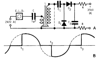
A light dimmer, a 1 µf capacitor and a 12 V car ignition coil form the simple line powered HV generator. The current in the dimmer is shown in Fig. B. At times tp t2, set by the dimmer switch, the inner triac of the dimmer switches on, and a very high and very fast current pulse charges the capacitor through the primary of the induction coil. 

Then at a rate of 120 times per second for a 60 Hz line, a very high voltage pulse appears at the secondary of the coil. To obtain an HV dc output, use a voltage doubler. Dl and D2 are selenium rectifiers (TV 18 Siemens or ITT) used for the supply of television sets. High value output shock protection resistors, R, are recommended when suitable. 

 Build a high-volt supply Circuit Diagram

Build a high-volt supply Circuit Diagram

Read More..

Friday, July 12, 2013

Build a LT3582 12 DC 5V to 12V DC Converter

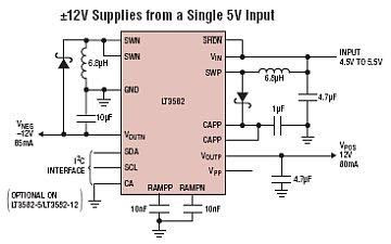
Using LT3582-12 dual channel DC DC converter integrated circuit, manufactured by Linear Technology, can be designed a very simple step up dc converter. This 5 to 12V c converter electronic project provide both positive and negative outputs required in many biasing applications such as active matrix OLED (organic light-emitting diode)displays as well as CCD (charge coupled device) applications.

Build a LT3582-12 DC 5V to 12V DC Converter

The LT3582 offer an I2C interface that can dynamically program output voltages, power sequencing and output voltage ramps as the application requires. The LT3582’s positive output voltage can be set between 3.2V and 12.775 in 25mV steps, whereas the negative output can be set between -1.2V and -13.95V in 50mV steps. The LT3582-12 is preconfigured with ±12V output, requiring no future programming.
Read More..

Build a 65W Notebook Laptop Power Adapter

Using TOP269EG off-line switcher IC, (U1), in a flyback configuration can be designed a very simple high efficiency notebok laptop power adapter.TOP269EG IC has an integrated 725 V MOSFET and a multi-mode controller. It regulates the output by adjusting the MOSFET duty cycle, based on the current fed into its CONTROL pin.This laptop power adapter circuit will provide a fixed 19 volts output voltage at a maximum current of 3.5A. input voltage range is between 90 to 265VAC.


Common-mode inductors L3 and L4 provide filtering on the AC input. X class capacitor C1 provides differential filtering, and resistors R1 and R2 provide safety from shock if the AC is removed, by ensuring a path for C1 to discharge. This is required by safety agencies when the capacitor value exceeds 100 nF. Bridge rectifier D1 rectifies the AC input, and bulk capacitor C2 filters the DC.


Read More..

Build a Radio Wave Alarm

This simple circuit is sure to have the police beating a path to your door- however, it has the added advantage of alerting you to their presence even before their footsteps fall on the doormat.

Simple Radio Wave Alarm Circuit Diagram :
Build a Radio Wave Alarm

Notes :
  • The circuit transmits on Medium Wave (this is the small problem with the police). IC1a, together with a sensor (try a 20cm x 20cm sheet of tin foil) oscillates at just over 1MHz. This is modulated by an audio frequency (a continuous beep) produced by IC1b. When a hand or a foot approaches the sensor, the frequency of the transmitter (IC1a) drops appreciably.
  • Suppose now that the circuit transmits at 1MHz. Suppose also that your radio is tuned to a frequency just below this. The 1MHz transmission will therefore not be heard by the radio. But bring a hand or a foot near to the sensor, and the transmitters frequency will drop, and a beep will be heard from the radio.
  • Attach the antenna to a multiplug adapter that is plugged into the mains, and you will find that the Medium Wave transmission radiates from every wire in your house. Now place a suitably tuned Medium Wave radio near some wires or a plug point in your house, and an early-warning system is set up.
  • Instead of using the sheet of tin foil as the sensor, you could use a doorknob, or burglar bars. Or you could use a pushbutton and series resistor (wired in series with the 33K resistor - the pushbutton would short it out) to decrease the frequency of IC1a, so activating the system by means of a pushbutton switch. In this case, the radio would be tuned to a frequency just below that of the transmitter.
Read More..

Wednesday, June 12, 2013

The Upcoming Iphone Car Kit A Good Travel Partner To Drive

The standby capacity deficiencies and not charge in the car When you are enjoying the beauty of nature, is not bothering you by this embarrassment? You can not enjoy your favorite music on the road; When you are speeding on the highway, you can answer a important phone. Do you have encountered? Now the good new is coming.

The recent series against the iPhone and the iPod launched Six-vehicle equipment - aiPower CA601. Adjustable elastic support products, which support 90-degree rotation, to provide users with a variety of operation, standard USB output interface can not only charge for a variety of digital devices, car audio system can also realize the iPhone hands-free calls, the other , aiPower CA601 can also be iPhone and the iPods music through the FM transmitter to car stereo channels to play.
Many MP3 users to buy the car kit in order to enjoy music anytime, anywhere to bring the fun, aiPower CA601 taking into account the MP3 car kit, users can iPhone and iPod products within the audio file through the FM transmitter to car stereo playback channels This feature is not only practical, but also to restore the high-quality sound, giving the user unprecedented comfort.
And other commercial car kit is different, aiPower CA601 can adjust the angle of the stent, the fixed phone can support one end of the bracket rotated 90 degrees to meet the habits of different users, while for most users get used to the current iPhone Case issues, the Patriots designers have done in research and development CA601 sufficient time to consider the design of the stent, aiPower CA601 using a flexible design that allows the iPhone to any equipment, protective cover products easily into the holder, and ensure stable and firm.
I believe this aiPower CA601 will be your best travel companion.
Read More..

Saturday, April 13, 2013

Power Flip Flop Using A Triac

Modern digitals is vital for each huge version railroad system, and it gives a option to virtually every problem. Although ready-made merchandise are exorbitantly expensive, clever digitals hobbyists attempt to use a minimal number of parts to be triumphant in most useful results together with low prices. This strategy can be tested using the moderately atypical semiconductor power flip-flop described here. A flip-flop is a toggling circuit with two stable switching states (bistable multivibrator). It care fors its output state even in the absence of an enter pulse.

Flip-flops can simply be carried out the usage of triacs if no DC voltage is on hand. Triacs are also so inexpensive that they're often used by means of edition railway builders as semiconductor energy switches. The decisive advantage of triacs is that they're bi-directional, which implys they may be ready to be precipitated during both the positive and the bad half-cycle by means of making use of an AC voltage to the gate electrode (G). The polarity of the set off voltage is as a result irrelevant. Triggering with a DC present is additionally that you could assume of. Figure 1 presentations the circuit diagram of this type of energy flop-flop. A permanent magnet is suited to the version teach, and when it commutes from left to proper, the magnet switches the flip-flop on and off by approach of reed switches S1 and S2.

Circuit diagram:

In order for this to work in each guidance of commute, every other pair of reed switches (S3 and S4) is hooked up in parallel with S1 and S2. Briefly closing S1 or S3 triggers the triac. The RC network C1/R2, which acts as a section shifter, handles the trigger current. The present thru R2, C1 and the gate electrode (G) reaches its most price when the voltage throughout the load passes thru zero. This lead tos the triac to be precipitated anew for every half-cycle, despite the very fact that no pulse is current at the gate. It remains prompted till S2 or S4 is closed, which lead tos it to return to the blocking state.The load will likely be incandescent lamps within the station space (platform lighting) or a solenoid-operated instrument, any suchs a crossing gate. The LED connected across the output (with a rectifier diode) point outs the state of the flip-flop. 

The circuit shown here is designed for use in a edition railway machine, however there will no longer be any the purpose is it may not be used for different softwares. The reed switches may additionally be changed by customary pushbutton switches. For the frequently used TIC206D triac, which has a most current rating of four A, no heat sink is vital in this software except a load present exceeding 1 A should be supplied continuously or for a long time frame. If the switch-on or switch-off pulse shows to be insufficient, the worth of electrolytic capacitor C1 need to be elevated a little.
Author: R. Edlinger - Copyright: Elektor July-August 2004
Read More..

Thursday, April 11, 2013

A Car Battery Monitor

A close call on the road can really focus your mind on the importance of having a battery monitor in a car. I had been enjoying a pleasant week of travelling around the countryside at a leisurely pace and taking in the beautiful scenery each day. It wasnt until the final day, with the big rush to return home, that I had to drive at night.My home is deep in the country and on the road I was travelling the closest petrol station may be 80km away. I was travelling through an area that is full of open-cut coal mines and large heavily loaded semi-trailers constantly pound the roads, travelling at quite high speeds. It was around 8pm at night and everything was very dark no street lights or house lights anywhere.

Just as I was going up a hill, the lights began to dim and the engine coughed. A large semi-trailer loomed in the rear-vision mirror as I pushed the clutch in and tried to restart. My speed was falling rapidly and my lights were blacked out - I was like a sitting duck in the middle of the road, as the semi-trailer came rapidly bearing down on me. I just managed to pull the car off the road, as the semi-trailer came screaming past, missing me by inches! After calling for assistance from the NRMA, the problem was found to be a fault in the alternator, which was failing to charge the battery. The battery voltage had been falling under the heavy load of the lights and at the worst possible time, there was not sufficient power for the lights or the motor.

After the initial shock wore off, I put on my thinking cap to come up with a PIC-based solution to the problem. What was really needed was a display and a buzzer, to get my attention should the voltage fall outside a specified range. So my design criteria was set, a series of LEDs could indicate the voltage and a buzzer would also be used to warn of problems.
Main Features:
  • Visual indication of battery voltage
  • Audible warning when voltage becomes low
  • Screw terminals for easy connection
  • Simple and easy to build
Circuit details:

The circuit is based on PIC16F819 18-pin microcontroller which has an analog-to-digital (A/D) input to monitor the battery voltage and outputs capable of driving LEDs directly, to keep the component count down. There are seven LEDs in all, giving a good range of voltage indication. The topmost LED, LED1, comes on for voltages above 14V which will occur when the battery is fully charged. LED2 indicates for voltages between 13.5V and 14V while LED3 indicates between 13V and 13.5V. Normally, one of these LEDs will be on. LED4 covers 12.5V to 13V while LED5 covers 12V to 12.5V. LED6 covers from 11.5V to 12V while LED7 comes on for voltages below 11.5V. These two LEDs are backed up by the piezo chime which beeps for voltages between 11.5V and 12V and becomes more insistent for voltages below 11.5V.

That might seem fairly conservative. After all, most cars will start with no troubles, even though the battery voltage might be a touch below 12V, wont they? Well, no. Some modern cars will happily crank the motor at voltages below 11V but their engine management will not let the motor start unless the voltage is above 11V. So dont think that a modern car will always start reliably. This little battery monitor could easily prevent a very inconvenient failure to start! So lets describe the rest of the circuit. The incoming supply is connected via diode D1 which provides protection against reverse polarity while zener diode ZD1 provides protection from spike voltages.

A standard 7805 3-terminal regulator is then used to provide a stable 5V to the microcontroller. The battery voltage is sensed via a voltage divider using 33kΩ and 100kΩ resistors. This brings the voltage down to within the 0-5V range for the A/D input of the PIC16F819. Port B (RB0 to RB7) of the microcontroller is then used to drive the various LEDs, with current limiting provided via the 330Ω resistor network. RB7, pin 13, drives a switching transistor for the piezo buzzer.

Software:
For the software, the design follows the basic template for a PIC microcontroller. Port A and its ADC (analog-to-digital converter) function are set up while port B functions as the output for the LEDs and buzzer. Once the set-up is complete, a reading will be taken at port RA2, the input for the A/D convertor. This reading is then compared with a series of values to determine the range of the voltage. This is similar to a series of "if" statements in Basic language. If the voltage is found to be within a certain range, the relevant port B pin will be turned on. If the voltage is below 12V, the buzzer will be turned on for a brief period, to signal a low battery condition. As the voltage falls below 11.5V, the frequency of the beeps will increase, to signal increased urgency.

Building it:

All the parts are mounted on a small PC board measuring 46 x 46mm (available from Futurlec). The starting point should be the IC socket for the PIC16F819, as this is easiest to mount while the board is bare. The next item can be the PC terminal block. The resistors and capacitors can then follow. Make sure the electrolytics are inserted with correct polarity.

Make sure that you do not confuse the zener (ZD1) with the diode when you are installing them; the diode is the larger package of the two.
 
Even more important, dont get the 78L05 3-terminal regulator and the 2N3906 transistor mixed up; they come in identical packages. The 78L05 will be labelled as such while the 2N3906 will be labelled "3906". And make sure you insert them the correct way around. The buzzer must also be installed with the correct polarity. The 330Ω current limiting resistors are all in a 10-pin in-line package. There are four green LEDs, two yellow and one red. They need to be installed in line and with the correct orientation.

Testing:

Before you insert the PIC16F819 microcontroller, do a voltage check. Connect a 12V source and check for the presence of 5V between pins 14 & 5 OF IC1. If 5V is not present, check the polarity of regulator REG1 and the polarity of the diode D1. If these tests are OK, insert the IC and test the unit over a range of voltage between 9V and 15V. Make sure that all LEDs come on in sequence and the piezo buzzer beeps for voltages below 12V. 

Now it is matter of installing the unit in your car. It is preferable to install the unit in a visible position for the driver. However, it should not obscure any other instruments. The unit should be connected to the cars 12V supply after the ignition switch. This will turn the unit off with the other instruments and prevent battery drain while the motor is not running.


Author :Alan Bonnard
Read More..

Tuesday, March 26, 2013

A Simple Yet Useful Video Switcher

With the cost of security cameras going down, adding a surveillance system for your store, office or home is becoming more practical all the time. However, you might be dismayed at the thought of having to buy a monitor for every camera that’s installed. dedicating a single monitor to a single camera also runs the risk of burning the camera’s image into the phosphor screen of the CRT. If you prefer a single monitor instead of the “NASA-Mission Control” look, you could buy a special monitor that has a video switcher built in. That type of monitor can automatically switch between several camera inputs in sequence.

With that type of arrangement, you’d have to watch only one screen instead of having to scan a wall of CRTs. Switching between several cameras would also prevent image burn-in on the monitor. Those types of monitors, unfortunately, are also very expensive, offsetting the cost savings of even the cheapest surveillance camera. Video switchers are also available, but the cost of a switcher and a monitor could be as expensive as a monitor/switcher combination unit. A viable alternative for a video switcher is to build your own. Thanks to some recently introduced ICs, the cost and effort of designing and building such a unit has become both quite affordable and easy.


The video switcher described here can display the output of two, three, or four cameras on a single monitor. The number of cameras is set by a DIP switch on the circuit board. That feature avoids blank displays if less than four cameras are used by sequencing through only the inputs that are connected to a camera. In the automatic mode, the cameras are switched at a rate that can be varied with a panel mounted control. The switching rate can be set from about once per second to about once every 20 seconds. In the manual mode, one camera output is displayed continuously. A momentary-toggle switch is then used to step through the various cameras.

How it works

The heart of the video switcher is a Maxim MAX454. That integrated circuit contains a four-way video multiplexer and an amplifier that operates as a low-impedance line driver. The resulting video output is high quality with very low phase distortion. The video inputs are selected by applying a binary number to the address inputs. The binary number is also used to light a series of LEDs that indicate whichh camera input is currently selected. The circuit is powered by a 9-volt AC wall-adapter transformer, two diodes, and two voltage regulators.

Circuit description

Figure 1 is a schematic diagram of the video switcher. Multiplexer IC1 has four video inputs, two address inputs, one video output, one external amplifier input, and and three power terminals. The video cameras connect to the video inputs through J1-J4. The inputs are terminated with 75 ohm resistors R1-R4. The gain of the internal video amplifier is set by a feedback network connected to pin 13 of IC1. That feedback network consists of R5-R8 and C3. The gain is set to 2 in order to compensate for any loss through the 75 ohm terminator resistor, R9. The resulting net gain is 1 at output J5.

The binary addressing circuit is built around IC2, a CD4017 decade counter. That chip produces one positive output at a time on each of its ten outputs in sequence for every clock pulse. The first four outputs at pins 3,2,4,and 7 are connected to transistors Q1- Q4. Those transistors drive LED1-LED4 through current limiting resistor R15. The outputs from IC2 (pins 2,4, and 7) are also decoded into binary logic by diodes D1-D4. The binary logic is sent to the address input lines of IC1.


The number of cameras connected to the video switcher is set with S1. Each switch in S1 is connected to an output from IC2. If, for example, there are only two cameras connected to the video switcher, S1-a is closed. That connects the third output to IC2’s reset line. When IC2 advances to the third count, that output passes through S1-a to the reset, and IC2 resets to zero, activating the first camera. The sequence would be camera 1, camera 2, then back to camera 1. Closing S1-b or S1-c instead of S1-a will let the video switcher cycle through three or four cameras, respectively.

Clock pulses for the counter are generated by IC3, an LMC555 CMOS timer. The pulse rate and pulse width is controlled by C4, R10, R11 and potentiometer R12. By adjusting R12, the output frequency of IC3 can be controlled between 1 Hz and 1/20 Hz. The clock pulses from IC3 are connected to IC2 through S2, a three position toggle switch. Switching S2 to the auto position lets the pulses from IC3 select the next camera at a rate set by R12. When S2 is in its center-off position, no switching takes place, and whatever camera input is selected is passed through to the output.


The select position on S2 is a momentary contact. That position raises the clock input of IC2 to 5 volts, which increments the binary count and selects the next camera. When S2 is released, it springs back to its center-off position. The clock input of IC2 is then held at a low-logic level by R13. The MAX454 requires ±5 volts while the other ICs require only +5 volts. Power is supplied by AC adapter T1, rectifier diodes D5 and D6, regulators IC4 and IC5, and filter capacitors C6-C9.

Construction

Because of the high frequency video signals involved, the video switcher should be built on a printed circuit board. The circuit is simple enough to fit onto a single-sided board with only two jumpers needed. A foil pattern is included for etching and drilling your own board. Alternatively, an etched board can be purchased from the source given in the parts list. A feature of that board design is ground traces that run between all of the video signal traces in order to keep induced noise and crosstalk between the signals to a minimum.

Weather you etch a board from the foil pattern or purchase one from the source in the parts list, use the parts-placement diagram in fig. 2 for component placement. It is easiest to install and solder the resistors and diodes first. Once those components are in place, scrap component leads can be used for the two jumper wires. Next, install S1 and sockets for IC2 and IC3. Do not use a socket for IC1, the MAX454 multiplexer.

When installing J1-J5, hold the connectors tight against the board while soldering the center pin. The assembly can then be placed on a heat-resistant surface and the ground pins soldered. Because of their size and mass, a larger soldering iron might be needed to solder J1-J5. Otherwise the board might be damaged if heat is applied too long. Once the connectors are soldered in place, Q1-Q4, IC4, IC5, and all the capacitors can be installed. The LEDs should be installed next, leaving their leads long so that they can be bent to reach through the front panel of the enclosure.

Double-check the orientation of the polarized components, so that they are not installed backwards by accident. Once a component is soldered in place, removing it becomes much more difficult. Solder two 3-inch long wires onto the two terminals of R12 that are clockwise when viewing the potentiometer from the back. Connect those wires to the holes for R12 on the board. Three additional 3-inch long wires are soldered onto the terminals of S2. The center terminal connects to the hole near C5 and R13.

The momentary-contact terminal connects to the hole near R14. The remaining terminal connects to the hole near IC3 and R10. Solder IC1 directly onto the circuit board. That will result in the shortest possible lead length for the video signals. Plug IC2 and IC3 into their sockets, being careful to handle them as static-sensitive CMOS devices. Solder the T1 leads onto the board. Examine the board for any wiring errors, bad solder joints, and incorrect components. Once the assembly is inspected, it can be tested.

Testing

Plug T1 into an AC outlet and measure the voltages across C8 nd C9. The voltage across C8 should measure +5 volts. Across C9, the voltage should be -5 volts. To select two cameras, set S1-a on; to select three cameras, set set S1-b on; and to select all four cameras, set S1-c on. Only one switch at a time should be on. When switch S2 is toggled to its momentary position, the LEDs should sequence to the next indicator each time S2 is toggled. The order of the LEDs should cycle from 1 through 4 and repeat. When S2 is set to automatic, the LEDs should automatically at a rate that should vary as potentiometer R12 is adjusted. Connect cameras to J1-J4 and a monitor to J5.

The video signal on the monitor should switch from camera to camera according to the LEDs. After testing is completed, drill appropriate holes in a suitable enclosure for J1-J5, LED1-LED4, S2, and R12. Mount the board in the enclosure using the mounting hardware for J1-J5 to hold it in place. Mount R12 and S2 in the front panel and bend the LEDs so they fit through the holes in the panel. The hole for the T1 wire should be drilled at a point where the two halves of the enclosure meet.

Tie a knot in the wire for strain relief and place the wire in the enclosure hole with the knot on the inside of the enclosure before closing the case. That completes the project. If all has gone well, as is likely, your video switcher is now ready for use.

SEMICONDUCTORS
  • IC1 - MAX454 multiplexer, integrated circuit (MAXIM)
  • IC2 - CD4017 decade counter, integrated circuit
  • IC3 - LMC555 timer, integrated circuit
  • IC4 - 78l05 voltage regulator, integrated circuit
  • IC5 - 79l05 voltage regulator, integrated circuit
  • Q1-Q4 - MPSA14, NPN transistor
  • D1-D4 - 1N914, silicon diode
  • D5, D6 - 1N4004, silicon diode
  • LED1-LED4 - Light emitting diode, red
RESISTORS
  • R1-R4, R9-R15 - 75 ohm
  • R5 - 150,000 ohm
  • R6 - 620 ohm
  • R7 - 1100 ohm
  • R8 - 1000 ohm
  • R10 - 10,000 ohm
  • R11 - 51,000 ohm
  • R12 - I megohm potentiometer, panel mount
  • R13, R14 - 100,000 ohm
CAPACITORS
  • C1,C2,C5 - 0.1mF, 50WVDC, metalized film
  • C3 - 6.8 pF, ceramic disc
  • C4 - 10 mF, 50 WVDC, low leakage electrolytic
  • C5, C7 - 470 mF, 25 WVDC, electrolytic
  • C8, C9 - 100 mF, 16 WVDC, electrolytic
ADDITIONAL PARTS AND MATERIALS
  • S1 - DIP switch, 3 position
  • S2 - Toggle switch, single pole double throw, one momentary position
  • J1-J5 - Video connector, chassis mount, “F” type
  • T1 - 9 volt AC wall adapter transformer, PC board, IC sockets, LED holders, 22 gauge hookup wire, knob, enclosure, hardware, etc.
Source: Electronics Now 1997
Read More..