Showing posts with label with. Show all posts
Showing posts with label with. Show all posts
Thursday, July 11, 2013
Digital Clock with Timer and Solar Panel Regulator
This is a combination digital clock timer and solar panel charge controller used to maintain a deep cycle battery from a solar panel. The timer output is used to control a 12 volt load for a 32 minute time interval each day. Start time is set using 9 dip switches and ends 32 minutes later. The 32 minute duration is set by selecting the 5th bit (2^5 = 32) of a 4040 binary counter (pin 2). The timer also has a manual toggle switch so the load can be manually switched on or off and automatically shuts off after 32 minutes. The time duration can be longer or shorter (8,16,32,64,128,256 minutes etc.) by selecting the appropriate bit of the counter. The timer circuit is shown in the lower schematic just above the regulator.
Basic Clock Circuit diagram
The basic clock circuit (top schematic below) is similar to the binary clock (on another page) and uses 7 ICs to produce the 20 digital bits for 12 hour time, plus AM and PM. A standard watch crystal oscillator (32,768) is used as the time base and is divided down to 1/2 half second by the 4020 binary counter. One half of a 4013 data latch is used to divide the 1/2 second signal by 2 and produce a one second pulse that drives the seconds counter (74HC390 colored purple). The minutes are advanced by decoding 60 seconds (40 + 20) and then resetting the seconds counter to 0 and at the same time advancing the minutes counter. The same procedure is used to advance the hours. The second half of the 4013 latch is used to indicate AM or PM and is toggled by decoding 13 hours and resetting the hours to 0 and then advancing the hours to "one".
Clock Display Circuit diagram
The clock display circuit is shown in the second drawing below and uses 6 more ICs to decode the binary data and drive four seven segment LED displays. The 10s of hours digit is driven with a single 3904 transistor. Two multiplexer circuits (4053) are used to manually select either minutes or seconds for the right two display digits. The two switches shown between the 4053s and below the left 4053 are both part of one DPDT switch which selects either seconds or minutes for the 1X and 10X digits. This switch is shown in the seconds position and the hours digits are blanked with a low signal on pin 4 of the 4511.
The display can also be toggled on and off (totally blank) using a set/reset latch made from a couple 74HC00 NAND gates. A momentary DPDT switch is used to control the latch and toggle the display on or off. The second pole of this switch is used on the upper drawing (connected to the run/stop switch) to set the hours and minutes. Thus this same switch performs both functions of blanking the display and setting the time. The run/stop switch is shown in the normal running mode and supplies a low signal to a NAND gate which prevents accidental setting the time while the clock is running.
Clock Timer Circuit diagram
The run/stop switch also turns on the display (through the diode D2) when in the stop position. The procedure for setting the clock would be to set the (run/stop) switch the stop position and the (seconds/minutes) switch to the minutes position. Then toggle the momentary switch to set minutes and hours of the current time plus one minute. The clock can then be started with the run/stop switch at precisely the right time (+/- 0.5 seconds).
Voltage Regulator (13.6 volts)
The voltage regulator in the lower drawing maintains the battery at 13.6 volts and also supplies the clock and timer circuits with 4.3 volts. The charge LED indicator only comes on when the regulator is supplying max charge to the battery. When the battery voltage reaches 13.6 the regulator reduces the current to whatever is necessary to maintain the voltage and the charge indicator will turn off. The unit I built also included a battery condition indicator (voltmeter using 4 LEDs) to indicate the battery condition so that a failure of the regulator would be indicated by the charge indicator LED turned off and less than 4 LEDs lit on the voltmeter.
Basic Clock Circuit diagram
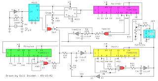 |
The basic clock circuit (top schematic below) is similar to the binary clock (on another page) and uses 7 ICs to produce the 20 digital bits for 12 hour time, plus AM and PM. A standard watch crystal oscillator (32,768) is used as the time base and is divided down to 1/2 half second by the 4020 binary counter. One half of a 4013 data latch is used to divide the 1/2 second signal by 2 and produce a one second pulse that drives the seconds counter (74HC390 colored purple). The minutes are advanced by decoding 60 seconds (40 + 20) and then resetting the seconds counter to 0 and at the same time advancing the minutes counter. The same procedure is used to advance the hours. The second half of the 4013 latch is used to indicate AM or PM and is toggled by decoding 13 hours and resetting the hours to 0 and then advancing the hours to "one".
Clock Display Circuit diagram
 |
The clock display circuit is shown in the second drawing below and uses 6 more ICs to decode the binary data and drive four seven segment LED displays. The 10s of hours digit is driven with a single 3904 transistor. Two multiplexer circuits (4053) are used to manually select either minutes or seconds for the right two display digits. The two switches shown between the 4053s and below the left 4053 are both part of one DPDT switch which selects either seconds or minutes for the 1X and 10X digits. This switch is shown in the seconds position and the hours digits are blanked with a low signal on pin 4 of the 4511.
The display can also be toggled on and off (totally blank) using a set/reset latch made from a couple 74HC00 NAND gates. A momentary DPDT switch is used to control the latch and toggle the display on or off. The second pole of this switch is used on the upper drawing (connected to the run/stop switch) to set the hours and minutes. Thus this same switch performs both functions of blanking the display and setting the time. The run/stop switch is shown in the normal running mode and supplies a low signal to a NAND gate which prevents accidental setting the time while the clock is running.
Clock Timer Circuit diagram
 |
The run/stop switch also turns on the display (through the diode D2) when in the stop position. The procedure for setting the clock would be to set the (run/stop) switch the stop position and the (seconds/minutes) switch to the minutes position. Then toggle the momentary switch to set minutes and hours of the current time plus one minute. The clock can then be started with the run/stop switch at precisely the right time (+/- 0.5 seconds).
Voltage Regulator (13.6 volts)
 |
The voltage regulator in the lower drawing maintains the battery at 13.6 volts and also supplies the clock and timer circuits with 4.3 volts. The charge LED indicator only comes on when the regulator is supplying max charge to the battery. When the battery voltage reaches 13.6 the regulator reduces the current to whatever is necessary to maintain the voltage and the charge indicator will turn off. The unit I built also included a battery condition indicator (voltmeter using 4 LEDs) to indicate the battery condition so that a failure of the regulator would be indicated by the charge indicator LED turned off and less than 4 LEDs lit on the voltmeter.

Wednesday, July 10, 2013
Simple HiFi Expandor Circuit Diagram with De emphasis
This is the schematic design of HiFi Expandor Circuit with De-emphasis. The circuit is based NE570. The NE570 can be used to construct a high performance compandor suitable for use with music. This type of system can be used for noise reduction in tape recorders, transmission systems, bucket brigade delay lines, and digital audio systems. The circuits to be described contain features which improve performance, but are not required for all applications.
HiFi Expandor Circuit Diagram

The expandor to complement the compressor is shown in the above circuit. Here an external op amp is used for high slew rate. Both the compressor and expandor have unity gain levels of 0dB. Trim networks are shown for distortion (THD) and DC shift. The distortion trim should be done first, with an input of 0dB at 10kHz. The DC shift should be adjusted for minimum envelope bounce with tone bursts. When applied to consumer tape recorders, the subjective performance of this system is excellent.
Wednesday, April 10, 2013
Multiplexer with TTL IC 74251
Actually you can not bother to design a multiplexer using logic gates because it has many special IC which functioned for a multiplexer.

One of the TTL ICs from the family that you can use to fulfill the function of a multiplexer is IC 74 251. At the IC there are 8 input channels and 3-bit selector and the other lane as a control reset and inverting output. As a note if you are using TTL ICs for your electronic circuit, the voltage supply that is allowed a maximum of 5 volts. So you can be more familiar with the workings of this multiplexer ic, IC74251 consider the truth table below:
C | B | A | G | Y | W |
X | X | X | 1 | Z | Z |
0 | 0 | 0 | 0 | D0 | D0’ |
0 | 0 | 1 | 0 | D1 | D1’ |
0 | 1 | 0 | 0 | D2 | D2’ |
0 | 1 | 1 | 0 | D3 | D3’ |
1 | 0 | 0 | 0 | D4 | D4’ |
1 | 0 | 1 | 0 | D5 | D5’ |
1 | 1 | 0 | 0 | D6 | D6’ |
1 | 1 | 1 | 0 | D7 | D7’ |
Z = High impedance (off) | |||||
D0,D1…D7 = Representing the output of the input lines D | |||||
Monday, April 8, 2013
8V DC Power Supply With Over Voltage Protection
This 8V DC power supply was designed for use with an expensive piece of electronic equipment. It features full over-voltage protection as a precaution against regulator failure, either in the supply itself or inside the equipment it is powering. The circuit uses a conventional full-wave rectifier, followed by a 3-terminal voltage regulator (REG1) with appropriate filtering. When power is applied and switch S1 is in the "Run" position, REG1s output is fed to the load via a 500mA fuse and Schottky diode D3.
This also lights LED2 (yellow) and LED3 (green), which respectively indicate the presence of the unregulated and regulated voltages. D3 is there to protect the circuit against external voltage sources (eg, charged capacitors). A "crowbar" circuit comprising ZD1 and SCR1 provides the over-voltage protection. It works like this: if a fault develops (eg, REG1 short circuit) which causes the output voltage to rise above 9.1V, ZD1 turns on and applies a voltage to the gate of SCR1.
Circuit diagram:
If the voltage then continues to rise, SCR1 turns on (at about 10V) and "blows" the fuse. Zener diode ZD2 provides emergency over-voltage protection in case the "crowbar" circuit develops a fault. Switch S1 is provided so the operator can occasionally test the "crowbar" function. When S1 is switched to the "Test" position, the load is disconnected by S1b and the unregulated supply voltage is applied by S1a to the "crowbar" circuit, thus causing it to trigger. When this happenS, LEDs 2 & 3 (green and yellow) extinguish and LED1 (red) lights to indicate that the SCR has triggered. The SCR turns off again when S1 is switched back to the "Run" position.
Read More..
This also lights LED2 (yellow) and LED3 (green), which respectively indicate the presence of the unregulated and regulated voltages. D3 is there to protect the circuit against external voltage sources (eg, charged capacitors). A "crowbar" circuit comprising ZD1 and SCR1 provides the over-voltage protection. It works like this: if a fault develops (eg, REG1 short circuit) which causes the output voltage to rise above 9.1V, ZD1 turns on and applies a voltage to the gate of SCR1.
Circuit diagram:

8V DC Power Supply With Over-Voltage Protection Circuit Diagram
If the voltage then continues to rise, SCR1 turns on (at about 10V) and "blows" the fuse. Zener diode ZD2 provides emergency over-voltage protection in case the "crowbar" circuit develops a fault. Switch S1 is provided so the operator can occasionally test the "crowbar" function. When S1 is switched to the "Test" position, the load is disconnected by S1b and the unregulated supply voltage is applied by S1a to the "crowbar" circuit, thus causing it to trigger. When this happenS, LEDs 2 & 3 (green and yellow) extinguish and LED1 (red) lights to indicate that the SCR has triggered. The SCR turns off again when S1 is switched back to the "Run" position.
Author: L. Cox - Copyright: Silicon Chip Electronics
Sunday, April 7, 2013
Track the damage capacitors elco with ESR meter
All technicians must have the same experience that the old models of aircraft generally have several common Elco its dry or down in value, mainly found in many brands of china plane. Eco is dry can cause a variety of disorders that are sometimes difficult to trace or even be able to make certain parts do not work at all, especially if used on a circuit that works at such high frequency SMPS (Switch Mode Power Supply) and the horizontal. Elco dry technicians sometimes make headaches and time consuming when you track the damage.
 Many technicians get around this problem by directly replacing all existing Elko, the Elko-regardless of whether Elko is corrupt or not. It is generally quite successful. But sometimes the quality is not good substitutes Elko, so the damaged aircraft back after use for some time. Replace all of Elko is also a problem for yourself if the circuit is improved a lot using Elko. The use of ESR-meter proved to be the most appropriate choice to solve the above problems. We suggest that ESR-meter is a must-have tool for every technician after avo-meter.
Using ESR-meter weve made themselves at a cost of less than 50,000 rupiah we recorded a lot of advantages such as:
- Elko track damaged by the time more quickly because they do not need to remove the Elko (in-circuit tester) one by one.
- Elko only replaced damaged
- Can be used to check the quality of new and used Elko. It is certainly advantageous to utilize part of the former ex-change machine pcb. Sometimes the plane is damaged due to repeated just posted a new Elko was poor quality.
- Elko that if the check using the ohm-meter sometimes the results are deceptive. Because if you checked with ESR ESR-meter turns his already large.
- Can be used to check the flyback is short in the primary coil (between the B + with a pin-pin-collectors), def a short yoke, the power tranfo a short primer.
- To find out if re-chargeable batteries are still good. Re-chargeable battery that is damaged ESR was generally higher when compared to a still good.
- To keep track of printed lines leaking / short
- By comparing the capacitors are still good, ESR-meter can be used to check the value of thousands pf capacitor.
Note:
- ESR meter can not be to find Elko leak or short. Fortunately rare short Elko damage.
- ESR meter to check the fit only Elko with values ranging 0.47uF and above.
Does ESR it actually?Parameters are generally owned by a Elko understood by engineers is the "maximum working voltage" and "capacitance value". In the real case there are several other parameters such as the "maximum working temperature" (85 or 105 degrees C) and "ESR" (Equivalent Series Resistance).Unless the practice is capacitive in Elko also has the characteristics of "resistive" caused by a combination of resistance to the legs, internal connections, plates and electrolyte. Thus form a resistive characteristic ESR, because if it is portrayed as if such be installed in series with the capacitance of Elko.Ideally, an Elko ESR is zero, but in practice this is impossible.Elko High voltage tends to have larger ESR than the low voltage ElkoElko with small values tend to have higher ESR values greater than Elko.Elko 105 degrees (C) tend to have higher ESR than Elko 85 degrees (C).
What Is the ESR-meter?
ESR meter is a kind of ohm-meter that can be used to measure the amount of "resistance" of Elko. Difference if the ohm-meter using a dc current (direct current) to drive the meter, then use the ESR meter ac (alternating current) with a standard frequency 150Khz. As had been explained that ideally Elko its ESR is zero. But this is not possible in practice. Elko good quality 10uF value is close to zero or more generally.
What is the cause of ESR Elko subject to change.
- The first is caused because of the connection quality is poor constituents. It can be found in Elko Elko New and old.
- Both are caused due to dry the liquid electrolyte due to evaporate or leak, which can be found at the old Elko. Are the consequences of large ESR Elko turned into?
Consequences of changing the value of ESR Elko
- Elko is a working principle can be "in-fill and waste of" electric charge repeatedly. Thus ESR Elko-charging current will be passed this exile repeatedly in accordance with the working frequency of the circuit. And we certainly have understood that if bypassed resistor will generate heat flows in accordance with the magnitude of the current strength through resistance value and the corresponding magnitude. Similarly, the Elko with ESR, the greater the greater the ESR value of the heat arising in Elko, and the higher the frequency the greater the heat generated. This heat can eventually cause the electrolyte evaporates into a gas and seeped out, so the value of Elko will turn down. In the specific cases heat can even make Elko explode.
- On a circuit that works at high frequencies Elko should have zero resistance to the high frequency signal. If the ESR of the resistance turned into Elko is no longer zero, and if the resistance value change is large enough to make the workings of the chaotic circuit.
Our experience with the use of ESR meter in the aircraft repair older model (the old plane), the first one we always do is:
- Check out all the Elko with ESR-meter at the SMPS, Horizontal and Vertical and immediately replace it if the ESR problem.
- Check visually (with a magnifying glass if necessary) solder-solder on the SMPS, the output Horizontal, Vertical output, and the CRT socket pcb and soldering again if there appears a problem or suspicious solder it.
- Both of these were able to eliminate the difficulties that may arise and difficult to trace, so the use of ESR meter can shorten repair time.
How to use homemade ESR meter (calibration)
- Once the tool is finished
- Collect some old Elko is still good. Find Elko pcb traces of the plane, made in Japan or Europe the original (former aircraft engine change) because of generally good quality for use as a reference.
- Grouped on the basis of a value less dar 2.2uF, 4.7uF is less than, less than and greater than 10uF 10uF.
- Try using the ESR-meter to measure each group, and mark the position of the needle meter on each group
- These markers can be used as a reference to the appointment of Elko ESR is still good.
- If the meter needle to deviate less from the reference mark, the mean ESR Elko is not good.
Wednesday, April 3, 2013
Li Ion DRIVER WITH EXTERNAL PWM DIMMING ELECTRONIC DIAGRAM

Li-Ion DRIVER WITH EXTERNAL PWM DIMMING ELECTRONIC DIAGRAM
This boost converter is quite useful to improve conversion efficiency, reduce output ripple, and the use of small external components. In default, the LED current is set with external sensor resistor Rset, feed back voltage is regulated to 2000 miliVolts. During the operation, the current LED can be controlled using 1-wire digital interface through CTRL pin or with PWM signal that applied to the CTRL pin through the duty cycle. It determines the feedback reference voltage. The device also has a feature of integrated open LED protection that will disable the boost converter, this is to prevent the output from exceeding the absolute maximum ratings during open LED condition.
- L1: Murata LQH3NPN100NM0
- C1: Murata GRM188R61A105K
- C2: Murata GRM188R61E474K
- D1: ONsemi MBR0540T1
Tuesday, April 2, 2013
Surround Amplifier Circuit with TDA7053
Surround Amplifier Circuit with TDA7053
Read More..
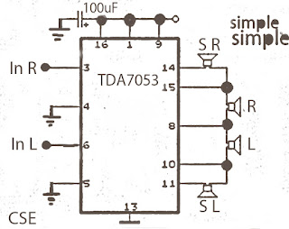
Perhaps the surround amplifier circuit below is an interesting circuit is made. For, making easy just by using the IC and electrolytic capacitor added 1 , we already can hear the strains of music with sound ( Front Left ,Right and surround Right , Left. In addition to listening to music , this amplifier is also very suitable for gamers who want good sound quality.
Minimum voltage requred 9 volts and maximum of 15 volts. Power Output of each speaker 10 Watt with 4 ohm impedance.
Subscribe to:
Posts (Atom)