Showing posts with label for. Show all posts

Saturday, July 13, 2013

Test Beeper For Your Stereo

The test beeper generates a sinusoidal signal with a frequency of 1,000 Hz, a common test  frequency for audio amplifiers.  It consists of a classical Wien- Bridge oscillator (also known as  a Wien-Robinson oscillator). The network that determines the  frequency consists here of a series connection of a resistor and  capacitor (R1/C1) and a parallel connection (R2/C2), where  the values of the resistors and  capacitors  are  equal  to  each  other. This network behaves, at  the oscillator frequency (1 kHz  in this case), as two pure resistors. The opamp (IC1) ensures  that the attenuation of the net- work  (3  times)  is  compensated  for.  In  principle  a  gain  of  3 times should have been sufficient to sustain the oscillation,  but  that  is  in  theory.  Because  of tolerances in the values, the  amplification needs to be (automatically) adjusted.

Circuit diagram:
Test Beeper For Your Stereo circuit-Diagram
Test Beeper For Your Stereo circuit Diagram

Instead of an intelligent amplitude  controller  we  chose  for  a  somewhat simpler solution. With  P1, R3 and R4 you can adjust  the gain to the point that oscillation takes place. The range of P1 (±10%) is large enough the cover the tolerance range. To sustain  the oscillation, a gain of slightly  more than 3 times is required,  which  would,  however,  cause  the amplifier to clip (the ‘round-trip’ signal becomes increasingly  larger, after all). To prevent this  from happening, a resistor in se-ries with two anti-parallel diodes  (D1 and D2) are connected in  parallel  with  the  feedback  (P1  and R3). If the voltage increases to the point that the threshold  voltage of the diodes is exceed-ed, then these will slowly start to  conduct.

The consequence of this  is that the total resistance of the  feedback  is  reduced  and  with  that  also  the  amplitude  of  the  signal. So D1 and D2 provide a  stabilising function. The distortion of this simple oscillator, after adjustment of P1 and  an output voltage of 100 mV (P2  to  maximum)  is  around  0,1%.  You can adjust the amplitude of  the output signal with P2 as required for the application. The  circuit is powered from a 9-V battery. Because of the low current  consumption  of  only  2 mA  the  circuit will provide many hours  of service.
Author :Ton Giesberts  - Copyright : Elektor Electronics
Read More..

Going for Gold

The title refers to a popular TV game show where the contestants each have a big button.  The  game show  host  asks  a  question and the first contestant to press their but-ton makes an illuminated indicator light up on their desk. The other contestants’ buttons  are automatically inhibited, so that everyone can see who was the first contestant to press their button, and so is allowed to answer the question. The project described here shows how to build a similar sortof  refereeing device yourself, using simple resources and without needing a microcontroller, which is  pretty rare these days! The basic circuit is for  just two contestants, but the modular design  means it can easily be expanded.

Circuit diagram :
 Going for Gold-Circuit-Diagram
Going for Gold Circuit Diagram

The diagram shows three buttons: S2 and S3  are the buttons for the two contestants, S1 is  the button for the host, which allows them to  reset the circuit before each fresh question.  The ‘brains’ of the circuit is IC1, a 4013 dual D-type flip-flop, of which only the Set and Reset  inputs are used here. This circuit can handle  quite a wide supply voltage range, from 3 to  15 V, and so the project can easily be run off a 4.5 V battery pack (the power consumption is minimal).

IC1 is armed by pressing S1 (reset). In this  state, the non-inverting outputs (pins 1 and  13) are at 0 and the inverting outputs (pins 12  and 12) are at 1. Hence line A is pulled high  by R1, since diodes D2 and D4 are not biased  on. If contestant 1 presses button S2, the  non-inverting output of flip-flop IC1a goes  to logic 1, and LED D1 lights via T1 to indicate that contestant 1 has pressed the but-ton. At the same time, the flip-flop’s invert-ing output goes to logic 0, making diode  D2 conduct. Line A is now pulled down to 0,  and consequently contestant 2’s button S3  can no longer trigger the second flip-flop.  The reverse happens if it is contestant 2 who  presses their button S3 first.

The circuit can be extended to 4 or 6 contest-ants (or even more) by adding a second or  third (or more) 4013 IC. All you have to do is  repeat the circuit (minus R1, R2, and S1) and connect to the A, B, Vdd, and 0 V lines on the right-hand side. 
 
 
Streampowers
Read More..

Monday, July 8, 2013

Electrical Isolation For I2C Bus

When the SDA (Serial DAta) lines on both the left and right lines are 1, the circuit is quiescent and optoisolators IC1 and IC2 are not actuated. When the SDA line at the left becomes 0, current flows through the LED in IC1 via R2. The SDA line at the right is then pulled low via D2 and IC1. Optoisolator IC2 does not transfer this 0 to the left, because the polarity of the LED in IC2 is the wrong way around for this level. This arrangement prevents the circuit holding itself in the 0 state for ever. As is seen, the circuit is symmetrical. So, when the SDA line at the right is 0, this is transferred to the left. The lower part of the diagram, intended for the SCL (Serial CLock) line, is identical to the upper part.

Circuit diagram :
Electrical isolation_for_I2C_bus_Circuit Diagram
Electrical Isolation For I2C Bus Circuit Diagram

Resistors R1, R4, R5, and R8, are the usual 3.3 kΩ pull-up resistors that are obligatory in each I2C line. If these resistors are already present elsewhere in the system, they may be omitted here. The current drawn by the circuit is slightly larger than usual since the pull-up resistors are shunted by the LEDs in the optoisolators and their series resistors. Nevertheless, it remains within the norms laid down in the I2C specification.


Source by : streampowers
Read More..

Wednesday, June 12, 2013

Remote Control circuits For Home Appliances

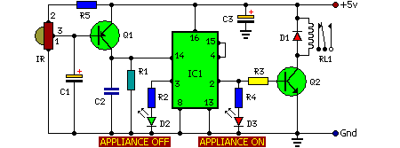
Here is the circuit diagram of Remote Operated Home Appliances or Remote controlled Home appliances. Connect this circuit to any of your home appliances (lamp, fan, radio, etc) to make the appliance turn on/off from a TV, VCD, VCR, Air Conditioner or DVD remote control. The circuit can be activated from up to 10 meters. It is very easy to build and can be assembled on a veroboard or a general-purpose PCB.

Parts:

R1 = 220K
R2 = 330R
R3 = 1K
R4 = 330R
R5 = 47R
C1 = 100uF-16V
C2 = 100nF-63V
C3 = 470uF-16V
D1 = 1N4007
D2 = Red LED
D3 = Green LED
Q1 = BC558
Q2 = BC548
IR = TSOP1738
IC1 = CD4017
RL1 = Relay 5V DC
 

The 38kHz infrared rays generated by the remote control are received by IR receiver module TSOP1738 of the circuit. Pin 1 of TSOP1738 is connected to ground, pin 2 is connected to the power supply through R5 and the output is taken from pin 3. The output signal is amplified by Q1. The amplified signal is fed to clock pin 14 of decade counter IC CD4017 (IC1). Pin 8 of IC1 is grounded, pin 16 is connected to vcc and pin 3 is connected to D2 (Red LED), which glows to indicate that the appliance is ‘off.’

The output of IC1 is taken from its pin 2. D3 connected to pin 2 is used to indicate the ‘on’ state of the appliance. Q2 connected to pin 2 of IC1 drives relay RL1.
D1 acts as a freewheeling diode. The appliance to be controlled is connected between the pole of the relay and neutral terminal of mains. It gets connected to live terminal of AC mains via normally opened (N/O) contact when the relay energizes. If you want to operate a DC 12 volt relay then use a regulated DC 12 volt power supply for DC 12 volt Relay and remember that the circuit voltage not be exceeded more than DC 5 volts.

Remote Control circuits For Home Appliances 

.

Read More..

Wednesday, May 29, 2013

Choosing the Right Amplifier for your Auto Sound System

Finding the best amplifier for your auto sound system can be a lot easier if you take the time ahead of time to learn what you need and what will work best with the sound system youve selected for your car, truck, or SUV. It helps to understand what an amplifier does in order to purchase the one that will best suit your needs. An amplifier takes a small sound, adds a little boost of its own, and then turns it into a big sound. The more power your amplifier has, the better quality of sound it will provide. An underpowered amplifier will have a thin, tinny sound that is rather unattractive in an auto sound system, or any other sound system for that matter.


You should also take care to remember that the power rating of an amplifier is the maximum power it is capable of expending not the amount that it will regularly use. The RMS rating of an amplifier is a good indication of its power output. One thing that is important to remember is that you should never buy an amplifier based on the maximum output or RMS rating. This number is more often than not incredibly misleading. If a driving, thumping bass beat is important to you then you should make sure that your amplifier has a bass boost button. This button will or switch will give a little bit of a boost to your bass. Its something I can pass on by many bass lovers cannot live without. Not all amplifiers have this so choose wisely and according to your preferences.

When it comes to amplifiers there are essentially four major classes (there are other classes but they are not all that common so I will not dwell on defining them) that represent the quality of sound you should expect from the system.

1) A. This class has a great output of quality sound but wastes huge amounts of energy in the process of creating that wonderful sound.

2) B. This class is slightly better than A as far as it wastes less energy and slightly worse as it produces a somewhat inferior quality of sound.

3) A/B. This resembles either A or B as far as sound and energy waste goes depending on the volume. Lower volumes will utilize the class A qualities of the amplifier while louder volumes are more in keeping with class B.

4) D. This class is primarily decent for producing a good bass sound and little else. The quality of sound and amount of energy wasted are both only moderate and neither are very impressive.

Of course this is the bare bones run through of the very basic amplifier basics. Another thing to note is that many people simply refer to amplifiers as amps rather than saying the entire word. Its slang but its so common that no one will blink if you do it. In fact you are far more likely to get funny looks for calling it an amplifier. Regardless of the small talk an amplifier isnt the end all be all of an auto sound system. It is only important if you feel it is important and many sound systems work splendidly without an extra amplifier to confuse the process and raise the price.

Whenever you decide to buy a new auto sound system for your car, truck, or SUV there is a moment of exhilaration and excitement as this is often a decision youve mulled over for quite a while rather than a spur of the moment decision. This exhilaration is promptly followed by a moment of complete and utter fear, as most of us have no clue what we really need. Hopefully, this has helped you decide whether or not you will need an amplifier and if you will, perhaps you can make a more educated and informed decision as to the type of amp you need.

Read More..

Monday, April 8, 2013

USB FM Transmitter for MP3 Player


This MP3 Player FM transmitter can be used to listen to your own music throughout your home. The transmitter circuit use no coils that have to be wound. When this FM transmitter used in the car, there is no need for a separate input to the car stereo to play back the music files from your MP3 player.

This FM transmitter use a chip made by Maxim Integrated Products, the MAX2606. The VCO (Voltage Controlled Oscillator) in this IC uses a Colpitts oscillator circuit.
The variable-capacitance (varicap) diode and feedback capacitors for
the tuning have also been integrated on this chip, so that you only
need an external inductor to fix the central oscillator frequency.


The supply voltage
to the IC should be between 2.7 and 5.5 V, the current consumption is
between 2 and 4 mA. With values like these it seemed a good idea to
supply the circuit with power from a USB port. A common-mode choke is connected in series with the USB connections in order to avoid interference between the circuit and the PC supply.

The
stereo signal connected to K1 is combined via R1 and R2 and is then
passed via volume control P1 to the Tune input of IC1, where it causes
the carrier wave to be frequency modulated. Filter R6/C7
is used to restrict the bandwidth of the audio signal. The setting of
the frequency (across the whole VHF FM broadcast band) is done with
P2, which is connected to the 5 V supply voltage.

The transmitter PCB designed uses resistors and capacitors with 0805 SMD packaging.
The size of the board is only 41.2 x 17.9 mm, which is practically
dongle-sized. For the aerial an almost straight copper track has been
placed at the edge of the board. In practice we achieved a range of
about 6 metres (18 feet) with this. There is also room for a 5-way SIL
header on the board. Here we find the inputs to the 3.5 mm jack plug,
the input to P1 and the supply voltage. The latter permits the circuit
to be powered independently from the mains supply, via for example
three AA batteries or a Lithium button cell. Inductor L1 in the
prototype is a type made by Murata that has a fairly high Q factor:
minimum 60 at 100 MHz.


Take
care when you solder filter choke L2, since the connections on both
sides are very close together. The supply voltage is connected to
this, so make sure that you don’t short out the USB supply! Use a
resistance meter to check that there is no short between the two supply
connectors before connecting the circuit to a USB port on a computer
or to the batteries.

P1 has the opposite effect to what you
would expect (clockwise reduces the volume), because this made the
board layout much easier. The deviation and audio bandwidth varies
with the setting of P1. The maximum sensitivity of the audio input is
fairly large. With P1 set to its maximum level, a stereo input of 10
mVrms is sufficient for the sound on the radio to remain clear. This
also depends on the setting of the VCO. With a higher tuning voltage
the input signal may be almost twice as large (see VCO tuning curve in
the data sheet). Above that level some audible distortion becomes
apparent. If the attenuation can’t be easily set by P1, you can
increase the values of R1 and R2 without any problems.

Measurements
with an RF analyzer showed that the third harmonic had a strong
presence in the transmitted spectrum (about 10 dB below the
fundamental frequency). This should really have been much lower. With a
low-impedance source connected to both inputs the bandwidth varies
from 13.1 kHz (P1 at maximum) to 57 kHz (with the wiper of P1 set to
1/10).

In this circuit the pre-emphasis of the input is missing. Radios in Europe have a built-in de-emphasis network
of 50 μs (75 μs in the US). The sound from the radio will therefore
sound noticeably muffled. To correct this, and also to stop a stereo
receiver from mistakenly reacting to a 19 kHz component in the audio
signal, an enhancement circuit is published elsewhere in this issue
(Pre-emphasis for FM Transmitter, also with a PCB). Author: Mathieu Coustans, Elektor Magazine, 2009


MP3 FM Transmitter Parts List
Resistors (all SMD 0805)
R1,R2 = 22kΩ
R3 = 4kΩ7
R4,R5 = 1kΩ
R6 = 270Ω
P1 = 10kΩ preset, SMD (TS53YJ103MR10 Vishay Sfernice, Farnell # 1557933)
P2 = 100kΩ preset, SMD(TS53YJ104MR10 Vishay Sfernice, Farnell # 1557934)
Capacitors (all SMD 0805)
C1,C2,C5 = 4μF7 10V
C3,C8 = 100nF
C4,C7 = 2nF2
C6 = 470nF
Inductors
L1 = 390nF, SMD 1206 (LQH31HNR39K03L Murata, Farnell # 1515418)
L2 = 2200Ω @ 100MHz, SMD, common-mode choke, 1206 type(DLW31SN222SQ2L Murata, Farnell #1515599)
Semiconductors
IC1 = MAX2606EUT+, SMD SOT23-6 (Maxim Integrated Products)
Miscellaneous
K1 = 3.5mm stereo audio jack SMD (SJ1-3513-SMT
CUI Inc, DIGI-Key # CP1-3513SJCT-ND)
K2 = 5-pin header (only required in combination with 090305-I pre-emphasis circuit)
K3 = USB connector type A, SMD (2410 07 Lumberg, Farnell # 1308875)


Notice. The use of a VHF FM transmitter, even a low power device like the one described here, is subject to radio regulations and may not be legal in all countries.
Read More..

Monday, April 1, 2013

Going for Gold

The title refers to a popular TV game show where the contestants each have a big button.  The  game show  host  asks  a  question and the first contestant to press their but-ton makes an illuminated indicator light up on their desk. The other contestants’ buttons  are automatically inhibited, so that everyone can see who was the first contestant to press their button, and so is allowed to answer the question. The project described here shows how to build a similar sortof  refereeing device yourself, using simple resources and without needing a microcontroller, which is  pretty rare these days! The basic circuit is for  just two contestants, but the modular design  means it can easily be expanded.

Circuit diagram :
 Going for Gold-Circuit-Diagram
Going for Gold Circuit Diagram

The diagram shows three buttons: S2 and S3  are the buttons for the two contestants, S1 is  the button for the host, which allows them to  reset the circuit before each fresh question.  The ‘brains’ of the circuit is IC1, a 4013 dual D-type flip-flop, of which only the Set and Reset  inputs are used here. This circuit can handle  quite a wide supply voltage range, from 3 to  15 V, and so the project can easily be run off a 4.5 V battery pack (the power consumption is minimal).

IC1 is armed by pressing S1 (reset). In this  state, the non-inverting outputs (pins 1 and  13) are at 0 and the inverting outputs (pins 12  and 12) are at 1. Hence line A is pulled high  by R1, since diodes D2 and D4 are not biased  on. If contestant 1 presses button S2, the  non-inverting output of flip-flop IC1a goes  to logic 1, and LED D1 lights via T1 to indicate that contestant 1 has pressed the but-ton. At the same time, the flip-flop’s invert-ing output goes to logic 0, making diode  D2 conduct. Line A is now pulled down to 0,  and consequently contestant 2’s button S3  can no longer trigger the second flip-flop.  The reverse happens if it is contestant 2 who  presses their button S3 first.

The circuit can be extended to 4 or 6 contest-ants (or even more) by adding a second or  third (or more) 4013 IC. All you have to do is  repeat the circuit (minus R1, R2, and S1) and connect to the A, B, Vdd, and 0 V lines on the right-hand side. 
 
 
Streampowers
Read More..

Wednesday, March 27, 2013

Automatic Switch For Voltage Converters

New applications for DC voltage converters, such as the ‘workhorse’ LT1070, arise every day. These converters can be adapted to nearly every imaginable ratio of input and output voltages. However, all of these circuits and devices have the same shortcoming, which is that they lack an on/off switch. Especially when they are used as a source of 6-V / 12-V power for a car radio, this is highly impractical. The circuit described here adds automatic load detection to the converter. For use in a car, the additional circuitry must be small and fit into a compact enclosure together with the converter.

Since the battery voltage and ambient temperature vary over wide ranges, a simple form of load detection must be used. Besides this, the voltage drop across the load sensing circuitry must naturally be as small as possible. This can be achieved by using ‘ultra-modern’ SiGe technology. The 6 V from the battery and the 12 V from the converter are combined in the MB R2545 dual diode. Consequently, a voltage of at least 6 V is always applied to the radio (for memory retention). If the radio is switched on, it draws a current from the 6-V battery, which may be around 100 mA.

This current produces a voltage across R1. If this voltage is 75 mV or greater, the AC128 germanium transistor starts conducting and charges electrolytic capacitor C1, which is connected to the gate of the BUZ10. The MOSFET energises RE1 and thus connects the supply voltage to the converter. As a result, 12-V power is connected to the radio. The resulting increased current causes the voltage drop across R1 to increase, which is undesirable, so a 10-A Schottky diode is connected in parallel. The total voltage drop is thus approximately 0.6 V. The RC network connected to the BUZ10 ensures that the transistor always remains switched on for at least several seconds, to prevent the circuit from ‘chattering’ with varying current consumption.

Automatic Switch Circuit Diagram For Voltage Converters
If the load is switched off, the AC128 cuts off, the electrolytic capacitor discharges and the relay again disconnects the voltage converter. The residual current consumption is so small that the circuit can also be connected ahead of the ignition switch. The Schottky diodes need only be rated for the necessary voltages and currents, and above all, they should have the lowest possible saturation voltage. The exact type is not critical. Two separate diodes can also be used. A small heat sink for the MBR diode won’t hurt, but this is normally not essential. Practically any type of PNP germanium transistor that is still available or on hand can be used (AC125, AC126 and AC128 work perfectly).

It may be necessary to modify the value of R1. In combination with the germanium transistor, R1 determines which level of current will be ignored (for memory retention) and which level of current will cause the converter to be switched on. With the component values shown in Figure 1, this level is between 10 mA and 25 mA. It is recommended to measure the quiescent current (at 6 V) and switch-on current of the load and then simulate the switching process using dummy load resistors. When selecting the 6-V relay, ensure that its contacts have an adequate current rating. The actual value can be significantly greater than the nominal output current. With a load of 5 A at 12 V and a converter efficiency of 70 percent, the current through the relay contacts rises to 14.3 A.
Read More..