Wednesday, June 12, 2013
Remote Control circuits For Home Appliances
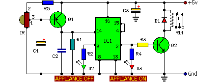
Here is the circuit diagram of Remote Operated Home Appliances or Remote controlled Home appliances. Connect this circuit to any of your home appliances (lamp, fan, radio, etc) to make the appliance turn on/off from a TV, VCD, VCR, Air Conditioner or DVD remote control. The circuit can be activated from up to 10 meters. It is very easy to build and can be assembled on a veroboard or a general-purpose PCB.
Parts:
R1 = 220K
R2 = 330R
R3 = 1K
R4 = 330R
R5 = 47R
C1 = 100uF-16V
C2 = 100nF-63V
C3 = 470uF-16V
D1 = 1N4007
D2 = Red LED
D3 = Green LED
Q1 = BC558
Q2 = BC548
IR = TSOP1738
IC1 = CD4017
RL1 = Relay 5V DC
The 38kHz infrared rays generated by the remote control are received by IR receiver module TSOP1738 of the circuit. Pin 1 of TSOP1738 is connected to ground, pin 2 is connected to the power supply through R5 and the output is taken from pin 3. The output signal is amplified by Q1. The amplified signal is fed to clock pin 14 of decade counter IC CD4017 (IC1). Pin 8 of IC1 is grounded, pin 16 is connected to vcc and pin 3 is connected to D2 (Red LED), which glows to indicate that the appliance is ‘off.’
The output of IC1 is taken from its pin 2. D3 connected to pin 2 is used to indicate the ‘on’ state of the appliance. Q2 connected to pin 2 of IC1 drives relay RL1. D1 acts as a freewheeling diode. The appliance to be controlled is connected between the pole of the relay and neutral terminal of mains. It gets connected to live terminal of AC mains via normally opened (N/O) contact when the relay energizes. If you want to operate a DC 12 volt relay then use a regulated DC 12 volt power supply for DC 12 volt Relay and remember that the circuit voltage not be exceeded more than DC 5 volts.
Remote Control circuits For Home Appliances
.

Saturday, March 30, 2013
Build a Tube Preamp for guitar with tone control
decided recently to build a tube preamp for my home studio. Please
note, however, that this is not a circuit for the novice electronics
builder. The circuit itself is simple, but unlike most semiconductor
projects, this one uses voltages near 300V. The danger of electrocution
is present and neither the author can assume responsibility for
protecting you.
If you are not familiar with good construction and
safety practices for high – voltage electronics, do not attempt to build
this circuit.
So how does it sound?
This
preamp won’t make the sound of an overdriven Marshall stack, nor is it a
heavy metal distortion unit, but it does produce tonal colors ranging
from a slight “warming” to soft distortion. Turning down the drive
control produces a somewhat brighter sound with no distortion? Turning
the drive all the way up produces distortion that really bites on the
bass strings and softens out on the higher notes. Driving the unit hard
also produces a bit of a compression effect. With my two – finger power
chord playing style, I find the overall effect quite pleasing.

Circuit description
The
preamp circuit, based on a design in the 1975 RCA Receiving Tube
Manual, uses a 12AX7 tube as a two stage, voltage gain amplifier.
This “generic” circuit is similar to what you will find in most guitar amp rpeamps.
The
12AX7 (6N2P and ECC83 are equivalent tubes) is probably the most common
tube used in the music business. Almost all current tube effects use
this tube, as do most vintage tube amps.
The 12AX7 was designed for
use in audio applications requiring exceptionally low hum and noise
levels. It is a high gain, twin triode device, having tow identical
sections sharing a common heater filament.
The guitar or other input feeds J1 and goes to the grid of the first tube stage, which produces a voltage gain of about 30.
This boosts the guitar’s 40 mV (nominal) input up to about up to about 1.2V.
Coupling
capacitor C2 picks off the amplified signal while blocking the high
voltage plate supply. The signal then goes through the tone control
circuit (R5-R9 and C3-C6) before feeding the second stage’s input.
Potentiometer R10 is a voltage divider that sets the drive.
The
second tube stage provides a gain of ten. The output signal couples
through blocking capacitor C8 to the load resistance (R13 and R14).
Control R14 varies the output signal level at J2, up to a maximum of
about 1.5V. this should feed a relatively high impedance stage; 600ohm
mixer inputs are not recommended. Resistors R4 and R12 are bias
resistors that allow the tube cathodes to develop a positive potential
with respect to ground. Capacitors C1 and C7 filter any ripple appearing
across these resistors.

POWER SUPPLY.
Transformer is a dual secondary type rated at 250VAC center-tapped for the tube’s plate supply and 6.3VAC for the tube filament.
The
output from a full-wave rectifier is 0.7 times the input AC voltage, so
about 185V appears across C10 and under load, about 140V appears
across.
Any transformer that produces 150 to 275VAC should work fine.
You
can also use a transformer with a 12VAC filament winding by grounding
ground pin 9 of the 12AX7 and running the 12VAC into pins 4 and 5.
PARTS LIST
R1, R5, R13------------47K 1/2W
R2----------------------1M 1/2W
R3, R8----------------100K 1/2W
R4---------------------2.2K 1/2W
R6, R9, R10-------------1M potentiometer
R7---------------------10K 1/2W
R11--------------------68K 1/2W
R12--------------------15K 1/2W
R14--------------------50K potentiometer
R15--------------------47K 1W
R16------------------220K 1/2W
C1, C7------------------25mf 62V
C2, C8-----------------220nf 400V ceramic disk
C3----------------------20nf 400V ceramic disk
C4, C6------------------1.2nf 400V ceramic disk
C5---------------------220pf 400V ceramic disk
C9, C10-------------33-47mf 400V electrolytic
D1 – D4------------------1N4004
F1-----------------------0.1A fuse
J1, J2--------------------phone jack
T------------------------2x250V 50ma 6V 1 A transformer
S1---------------------- -switch
Misc---------------------9-pin tube socket