Sunday, September 22, 2013
Low Power FM Transmitter
This article should satisfy those who might want to build a low power FM transmitter. It is designed to use an input from another sound source (such as a guitar or microphone), and transmits on the commercial FM band - it is actually quite powerful, so make sure that you dont use it to transmit anything sensitive - it could easily be picked up from several hundred metres away. The FM band is 88 to 108MHz, and although it is getting fairly crowded nearly everywhere, you should still be able to find a blank spot on the dial.
NOTE: A few people have had trouble with this circuit. The biggest problem is not knowing if it is even oscillating, since the frequency is outside the range of most simple oscilloscopes. See Project 74 for a simple RF probe that will (or should) tell you that you have a useful signal at the antenna. If so, then you know it oscillates, and just have to find out at what frequency. This may require the use of an RF frequency counter if you just cannot locate the FM band.
Description
The circuit of the transmitter is shown in Figure 1, and as you can see it is quite simple. The first stage is the oscillator, and is tuned with the variable capacitor. Select an unused frequency, and carefully adjust C3 until the background noise stops (you have to disable the FM receivers mute circuit to hear this).
 Figure 1 - Low Power FM Transmitter
Because the trimmer cap is very sensitive, make the final frequency adjustment on the receiver. When assembling the circuit, make sure the rotor of C3 is connected to the +9V supply. This ensures that there will be minimal frequency disturbance when the screwdriver touches the adjustment shaft. You can use a small piece of non copper-clad circuit board to make a screwdriver - this will not alter the frequency.
The frequency stability is improved considerably by adding a capacitor from the base of Q1 to ground. This ensures that the transistor operates in true common base at RF. A value of 1nF (ceramic) as shown is suitable, and will also limit the HF response to 15 kHz - this is a benefit for a simple circuit like this, and even commercial FM is usually limited to a 15kHz bandwidth.
Capacitors
All capacitors must be ceramic (with the exception of C1, see below), with C2 and C6 preferably being N750 (Negative temperature coefficient, 750 parts per million per degree Celsius). The others should be NPO types, since temperature correction is not needed (nor is it desirable). If you cannot get N750 caps, dont worry too much, the frequency stability of the circuit is not that good anyway (as with all simple transmitters).
How It Works
Q1 is the oscillator, and is a conventional Colpitts design. L1 and C3 (in parallel with C2) tunes the circuit to the desired frequency, and the output (from the emitter of Q1) is fed to the buffer and amplifier Q2. This isolates the antenna from the oscillator giving much better frequency stability, as well as providing considerable extra gain. L2 and C6 form a tuned collector load, and C7 helps to further isolate the circuit from the antenna, as well as preventing any possibility of short circuits should the antenna contact the grounded metal case that would normally be used for the complete transmitter.
The audio signal applied to the base of Q1 causes the frequency to change, as the transistors collector current is modulated by the audio. This provides the frequency modulation (FM) that can be received on any standard FM band receiver. The audio input must be kept to a maximum of about 100mV, although this will vary somewhat from one unit to the next. Higher levels will cause the deviation (the maximum frequency shift) to exceed the limits in the receiver - usually ±75kHz.
With the value shown for C1, this limits the lower frequency response to about 50Hz (based only on R1, which is somewhat pessimistic) - if you need to go lower than this, then use a 1uF cap instead, which will allow a response down to at least 15Hz. C1 may be polyester or mylar, or a 1uF electrolytic may be used, either bipolar or polarised. If polarised, the positive terminal must connect to the 10k resistor.
Inductors
The inductors are nominally 10 turns (actually 9.5) of 1mm diameter enamelled copper wire. They are close wound on a 3mm diameter former, which is removed after the coils are wound. Carefully scrape away the enamel where the coil ends will go through the board - all the enamel must be removed to ensure good contact. Figure 2 shows a detail drawing of a coil. The coils should be mounted about 2mm above the board.
For those still stuck in the dark ages with imperial measurements (grin), 1mm is about 0.04" (0.0394") or 5/127 inch (chuckle) - you will have to work out what gauge that is, depending on which wire gauge system you use (there are several). You can see the benefits of metric already, cant you? To work out the other measurements, 1" = 25.4mm
NOTE: The inductors are critical, and must be wound exactly as described, or the frequency will be wrong.
 Figure 2 - Detail Of L1 And L2
The nominal (and very approximate) inductance for the coils is about 130nH.This is calculated according to the formula ...
L = N² * r² / (228r + 254l)
... where L = inductance in microhenries (uH), N = number of turns, r = average coil radius (2.0mm for the coil as shown), and l = coil length. All dimensions are in millimetres.
Pre-Emphasis
It is normal with FM transmission that "pre-emphasis" is used, and there is a corresponding amount of de-emphasis at the receiver. There are two standards (of course) - most of the world uses a 50us time constant, and the US uses 75us. These time constants represent a frequency of 3183Hz and 2122Hz respectively. This is the 3dB point of a simple filter that boosts the high frequencies on transmission and cuts the same highs again on reception, restoring the frequency response to normal, and reducing noise.
The simple transmitter above does not have this built in, so it can be added to the microphone preamp or line stage buffer circuit. These are both shown in Figure 3, and are of much higher quality than the standard offerings in most other designs.
 Figure 3 - Mic And Line Preamps
Rather than a simple single transistor amp, using a TL061 opamp gives much better distortion figures, and a more predictable output impedance to the transmitter. If you want to use a dynamic microphone, leave out R1 (5.6k) since this is only needed to power an electret mic insert. The gain control (for either circuit) can be an internal preset, or a normal pot to allow adjustment to the maximum level without distortion with different signal sources. The 100nF bypass capacitors must be ceramic types, because of the frequency. Note that although a TL072 might work, they are not designed to operate at the low supply voltage used. The TL061 is specifically designed for low power operation.
The mic preamp has a maximum gain of 22, giving a microphone sensitivity of around 5mV. The line preamp has a gain of unity, so maximum input sensitivity is 100mV. Select the appropriate capacitor value for pre-emphasis as shown in Figure 3 depending on where you live. The pre-emphasis is not especially accurate, but will be quite good enough for the sorts of uses that a low power FM transmitter will be put to. Needless to say, this does not include "bugging" of rooms, as this is illegal almost everywhere.
I would advise that the preamp be in its own small sub-enclosure to prevent RF from entering the opamp input. This does not need to be anything fancy, and you could even just wrap some insulation around the preamp then just wrap the entire preamp unit in aluminum foil. Remember to make a good earth connection to the foil, or the shielding will serve no purpose.
Read More..
NOTE: A few people have had trouble with this circuit. The biggest problem is not knowing if it is even oscillating, since the frequency is outside the range of most simple oscilloscopes. See Project 74 for a simple RF probe that will (or should) tell you that you have a useful signal at the antenna. If so, then you know it oscillates, and just have to find out at what frequency. This may require the use of an RF frequency counter if you just cannot locate the FM band.
Description
The circuit of the transmitter is shown in Figure 1, and as you can see it is quite simple. The first stage is the oscillator, and is tuned with the variable capacitor. Select an unused frequency, and carefully adjust C3 until the background noise stops (you have to disable the FM receivers mute circuit to hear this).
 Figure 1 - Low Power FM Transmitter
Because the trimmer cap is very sensitive, make the final frequency adjustment on the receiver. When assembling the circuit, make sure the rotor of C3 is connected to the +9V supply. This ensures that there will be minimal frequency disturbance when the screwdriver touches the adjustment shaft. You can use a small piece of non copper-clad circuit board to make a screwdriver - this will not alter the frequency.
The frequency stability is improved considerably by adding a capacitor from the base of Q1 to ground. This ensures that the transistor operates in true common base at RF. A value of 1nF (ceramic) as shown is suitable, and will also limit the HF response to 15 kHz - this is a benefit for a simple circuit like this, and even commercial FM is usually limited to a 15kHz bandwidth.
Capacitors
All capacitors must be ceramic (with the exception of C1, see below), with C2 and C6 preferably being N750 (Negative temperature coefficient, 750 parts per million per degree Celsius). The others should be NPO types, since temperature correction is not needed (nor is it desirable). If you cannot get N750 caps, dont worry too much, the frequency stability of the circuit is not that good anyway (as with all simple transmitters).
How It Works
Q1 is the oscillator, and is a conventional Colpitts design. L1 and C3 (in parallel with C2) tunes the circuit to the desired frequency, and the output (from the emitter of Q1) is fed to the buffer and amplifier Q2. This isolates the antenna from the oscillator giving much better frequency stability, as well as providing considerable extra gain. L2 and C6 form a tuned collector load, and C7 helps to further isolate the circuit from the antenna, as well as preventing any possibility of short circuits should the antenna contact the grounded metal case that would normally be used for the complete transmitter.
The audio signal applied to the base of Q1 causes the frequency to change, as the transistors collector current is modulated by the audio. This provides the frequency modulation (FM) that can be received on any standard FM band receiver. The audio input must be kept to a maximum of about 100mV, although this will vary somewhat from one unit to the next. Higher levels will cause the deviation (the maximum frequency shift) to exceed the limits in the receiver - usually ±75kHz.
With the value shown for C1, this limits the lower frequency response to about 50Hz (based only on R1, which is somewhat pessimistic) - if you need to go lower than this, then use a 1uF cap instead, which will allow a response down to at least 15Hz. C1 may be polyester or mylar, or a 1uF electrolytic may be used, either bipolar or polarised. If polarised, the positive terminal must connect to the 10k resistor.
Inductors
The inductors are nominally 10 turns (actually 9.5) of 1mm diameter enamelled copper wire. They are close wound on a 3mm diameter former, which is removed after the coils are wound. Carefully scrape away the enamel where the coil ends will go through the board - all the enamel must be removed to ensure good contact. Figure 2 shows a detail drawing of a coil. The coils should be mounted about 2mm above the board.
For those still stuck in the dark ages with imperial measurements (grin), 1mm is about 0.04" (0.0394") or 5/127 inch (chuckle) - you will have to work out what gauge that is, depending on which wire gauge system you use (there are several). You can see the benefits of metric already, cant you? To work out the other measurements, 1" = 25.4mm
NOTE: The inductors are critical, and must be wound exactly as described, or the frequency will be wrong.
 Figure 2 - Detail Of L1 And L2
The nominal (and very approximate) inductance for the coils is about 130nH.This is calculated according to the formula ...
L = N² * r² / (228r + 254l)
... where L = inductance in microhenries (uH), N = number of turns, r = average coil radius (2.0mm for the coil as shown), and l = coil length. All dimensions are in millimetres.
Pre-Emphasis
It is normal with FM transmission that "pre-emphasis" is used, and there is a corresponding amount of de-emphasis at the receiver. There are two standards (of course) - most of the world uses a 50us time constant, and the US uses 75us. These time constants represent a frequency of 3183Hz and 2122Hz respectively. This is the 3dB point of a simple filter that boosts the high frequencies on transmission and cuts the same highs again on reception, restoring the frequency response to normal, and reducing noise.
The simple transmitter above does not have this built in, so it can be added to the microphone preamp or line stage buffer circuit. These are both shown in Figure 3, and are of much higher quality than the standard offerings in most other designs.
 Figure 3 - Mic And Line Preamps
Rather than a simple single transistor amp, using a TL061 opamp gives much better distortion figures, and a more predictable output impedance to the transmitter. If you want to use a dynamic microphone, leave out R1 (5.6k) since this is only needed to power an electret mic insert. The gain control (for either circuit) can be an internal preset, or a normal pot to allow adjustment to the maximum level without distortion with different signal sources. The 100nF bypass capacitors must be ceramic types, because of the frequency. Note that although a TL072 might work, they are not designed to operate at the low supply voltage used. The TL061 is specifically designed for low power operation.
The mic preamp has a maximum gain of 22, giving a microphone sensitivity of around 5mV. The line preamp has a gain of unity, so maximum input sensitivity is 100mV. Select the appropriate capacitor value for pre-emphasis as shown in Figure 3 depending on where you live. The pre-emphasis is not especially accurate, but will be quite good enough for the sorts of uses that a low power FM transmitter will be put to. Needless to say, this does not include "bugging" of rooms, as this is illegal almost everywhere.
I would advise that the preamp be in its own small sub-enclosure to prevent RF from entering the opamp input. This does not need to be anything fancy, and you could even just wrap some insulation around the preamp then just wrap the entire preamp unit in aluminum foil. Remember to make a good earth connection to the foil, or the shielding will serve no purpose.

Friday, September 20, 2013

Thursday, September 12, 2013
Simple Flashing LED
The circuit is designed to use very little current to prolong battery life so that it can be left on permanently. A superbright’ red LED is used because this provides a bright flash with a low current.
If you want to use 4.5V supply by connecting 3 Alkaline cells or any other source, change the resistor along with LED from 3.3k to 1k for a better flash.
Note that AA cells will last longer than a 9V PP3 battery
To flash two LEDs alternatively we have to increase the clock pulse speed to possibly fastest to have exact proper alternation.link
- 100k potentiometer
- 10k and 3.3k
- 10mF
- LED
- 555 Timer
- 9v Battery
There are three different modes to flash an LED using 555 Timer


and their bread board arrangements


Tuesday, September 10, 2013
Dual Basic Motor Speed Controllers Circuit Diagram
Here are two simple 12V DC motor speed controllers that can be built for just a few dollars. They exploit the fact that the rotational speed of a DC motor is directly proportional to the mean value of its supply voltage. The first circuit shows how variable voltage speed control can be obtained via a potentiometer (VR1) and compound emitter follower (Q1 & Q2). With this arrangement, the motor’s DC voltage can be varied from 0V to about 12V. This type of circuit gives good speed control and self-regulation at medium to high speeds but very poor low-speed control and slow starts. The second circuit uses a switchmode technique to vary motor speed.
Dual Basic Motor Speed Controllers Circuit Diagram fig 1

Here a quad NOR gate (IC1) acts as a 50Hz astable multivibrator that generates a rectangular output. The mark-space ratio of the rectangular waveform is fully variable from 20:1 to 1:20 via potentiometer VR1. The output from the multivibrator drives the base of Q1, which in turn drives Q2 and the motor. The motor’s mean supply voltage (integrated over a 50Hz period) is thus fully variable with VR1 but is applied in the form of high-energy "pulses" with peak values of about 12V.
Dual Basic Motor Speed Controllers Circuit Diagram fig 2

This type of circuit gives excellent full-range speed control and gives high motor torque, even at very low speeds. Its degree of speed self-regulation is proportional to the mean value of the applied voltage. Note that for most applications, the power transistor (Q2) in both circuits will need to be mounted on an appropriate heatsink.
Sourced by : Streampowers
Tuesday, September 3, 2013
Safety Polarity Connection
This electronic project prevents incorrect connection of polarized sources in circuit and is designed using common electronic components. Safety of polarity from the diagram below was dimensioned for a voltage of 12 volts. When connecting correctly voltage to terminals 1 and 2 through RE1 resting contact, diode D1 and the coil current flows once the switch closes the circuit (relay closing, established by contact or connection with device connected).
Safety Polarity Connection Circuit Diagram

When you connect the wrong polarity of power supply, diode D1 is blocked, the relay no longer closing and power is interrupted device. R1 resistance reduces current flowing through relay coil connected in the state, so that losses to be minimal (the resistance should be chosen according to characteristics of the relay).
Sunday, September 1, 2013
10 Channels Sensor Switch
A touch sensor switch circuit that works with 10 channels can be designed using electronic scheme in the figure below. If one of the 10 sensors is touched, the corresponding output goes in a logical state 1, the other inputs are in logic state 0.
10 Channels Sensor Switch Circuit Diagram

This 10 channel sensor switch is built using 4017 CMOS decimal counter which provides "decoded" signals. A second oscillator realized with CMOS logic gates produces clock signal. The counter is working until it achieved the desired position of the switch.
The switch can be supplied with a DC voltage between 3 and 15 volts DC.
10 Channels Sensor Switch Circuit Diagram

The switch can be supplied with a DC voltage between 3 and 15 volts DC.
Friday, August 30, 2013
Pressed Button Sound Indicator
sing this electronic scheme can be made an electronic circuit that allows a sound indication for a button.The circuit is based on a 7555 integrated timer (CMOS version of the well-known ment 555) is connected as a multivibrator astabil .His output is a rectangular pulse with a frequency of 700 Hz, which is used to control a small buzzer.
Pressed Button Sound Indicator Schematic
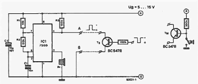
Pressed Button Sound Indicator Schematic
The circuit will oscillate be prevented if pin 4 of integrated circuit is connected to 0 V.
Subscribe to:
Posts (Atom)