Showing posts with label indicator. Show all posts
Showing posts with label indicator. Show all posts
Friday, August 30, 2013
Pressed Button Sound Indicator
sing this electronic scheme can be made an electronic circuit that allows a sound indication for a button.The circuit is based on a 7555 integrated timer (CMOS version of the well-known ment 555) is connected as a multivibrator astabil .His output is a rectangular pulse with a frequency of 700 Hz, which is used to control a small buzzer.
Pressed Button Sound Indicator Schematic
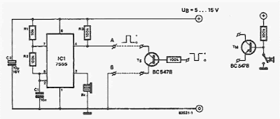
Pressed Button Sound Indicator Schematic
The circuit will oscillate be prevented if pin 4 of integrated circuit is connected to 0 V.

Sunday, July 7, 2013
Off Hook Telephone Line Indicator
The circuit is designed to connect in parallel with the telephone line, to monitor and detect if any telephone in the same line is busy, with the indication of the LED and which is self-powered so that it does not provide any load on a telephone line.
Light Emitting Diode (LED) – a semiconductor diode that is commonly a source of light when electric current pass through it Metal Oxide Semiconductor Field Effect Transistor (MOSFET) – a device utilized for switching and amplification of signals BS108 – a 250 mA and 200 Volts small signal MOSFET designed for high voltage, high speed switching applications such as relay drivers, CMOS logic, line drivers, TTL or microprocessor to high voltage interface and high voltage display drivers Diode Bridge – also known as bridge rectifier which has four diodes arranged in a bridge configuration where the output voltage has the same polarity with either polarity of the input voltage 1N4007 – a general purpose plastic rectifier with reverse voltage from 50 Volts to 1000 Volts and forward current of 1.0 Ampere
When none of the telephone lines is in use or on-hook, the voltage across the line is around 48V. In this state, the gate of transistor Q2 is shorted to its source during the conduction of Q1. This causes the LED to be disabled while Q2 is turned OFF. When one telephone extension along the telephone line changes to off-hook or in use condition, a voltage drop from 5V to 15V is detected. This will in turn cause Q1 to turn OFF because of the very low voltage across the gate of Q1 which is equal to 6% of the line voltage. Transistor Q2 then will be biased at around half of the line voltage.
Off-Hook Telephone Line Indicator Circuit Diagram
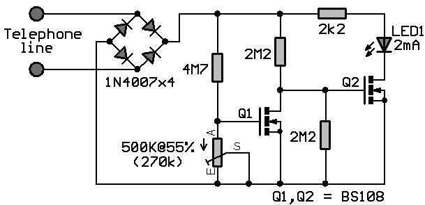
The sudden line drop of voltage triggers Q2 to light up the LED that will give a sign that the line is in use. Using the same line, the circuit is unseen with other telephone devices. A current-limiting resistor is used to maintain the low current of LED1 while the local telephone line parameters dictate the variation of other component’s values. The power of the circuit is provided by the telephone line. Other voltage protection may be used with some reliable design in addition to the current-limiting resistor. This is important to avoid any grounding effects from conducting surfaces within the circuit.
To ensure that transistor Q1 is fully biased while the line is free or not in use where LED1 is OFF, a 500K ohm MOSFET trimmer is used for the desired adjustment. A MOSFET is a three-terminal semiconductor component with a conducting channel in its output and a built-in capacitor at its input. To increase the values of any of the two resistors connected to the gate of Q2, a 200V MOSFET can be used in the place of Q2 if BS108 is not available. However, plain transistors like the bipolar junction can be used but with lower values to allow greater currents to pass through the line that is not in use. The bridge rectifier comprising of four 1N4007 diodes are performing the conversion of AC input into DC output.
MOSFET can function in two ways. The first is known as depletion mode wherein the channel shows its maximum conductance in the absence of a voltage on the gate. The second way that the MOSFET can function is known as enhancement mode wherein the device is not conducting even in the absence of a voltage on the gate because no channel is produced. A channel is being created with the application of a voltage to the gate. To generate better conductivity, greater voltage to the gate is required.
MOSFET drivers are applied in electronic motor control for different types of motors. Also, they are specifically used with long duty cycles, high operating frequency above 200 KHZ, lower output power, and wide load variations. The largest application of MOSFETs are the switched mode power supplies and in battery charging applications. In transducer drivers for high power devices such as light bulbs and motors, large current output with a small input is provided by MOSFETs. Since they are more non-linear than BJTs while producing less distortion, they can be utilized with Hi-Fi amplifiers. In constructing integrated circuits, MOSFETs are very useful since they can be made very compact. Although MOSFETs can get damaged by static electricity at higher voltages, they still provide several advantages as compared to other transistors which include faster switching time than BJT, lower losses than BJT, very small switching current, and least effects of temperature.
This telephone line indicator does not only tell when a telephone line is in use if a plurality of telephones are all setup to the same telephone line, but also prevents interruptions during personal calls. Additionally, it can also help to prevent costly and unwanted disruption of modem calls and fax, it alerts a person when a call is done and the phone is free to use, and the LED light indicates the line is in use.
To avoid any injury, it is a prerequisite to take extra precautionary measures when connecting any circuit to the telephone lines, which can produce life-threatening voltages during normal operation. During a lightning storm, it is better to keep distance from telephone lines.. Legal aspects are imposed in different countries for connecting things to telephone lines. The circuit should be better built with a plug-in cord for easy removal in case of fault occurrences. Otherwise, it would be best to consult a licensed telephone operator.
Light Emitting Diode (LED) – a semiconductor diode that is commonly a source of light when electric current pass through it Metal Oxide Semiconductor Field Effect Transistor (MOSFET) – a device utilized for switching and amplification of signals BS108 – a 250 mA and 200 Volts small signal MOSFET designed for high voltage, high speed switching applications such as relay drivers, CMOS logic, line drivers, TTL or microprocessor to high voltage interface and high voltage display drivers Diode Bridge – also known as bridge rectifier which has four diodes arranged in a bridge configuration where the output voltage has the same polarity with either polarity of the input voltage 1N4007 – a general purpose plastic rectifier with reverse voltage from 50 Volts to 1000 Volts and forward current of 1.0 Ampere
When none of the telephone lines is in use or on-hook, the voltage across the line is around 48V. In this state, the gate of transistor Q2 is shorted to its source during the conduction of Q1. This causes the LED to be disabled while Q2 is turned OFF. When one telephone extension along the telephone line changes to off-hook or in use condition, a voltage drop from 5V to 15V is detected. This will in turn cause Q1 to turn OFF because of the very low voltage across the gate of Q1 which is equal to 6% of the line voltage. Transistor Q2 then will be biased at around half of the line voltage.
Off-Hook Telephone Line Indicator Circuit Diagram
The sudden line drop of voltage triggers Q2 to light up the LED that will give a sign that the line is in use. Using the same line, the circuit is unseen with other telephone devices. A current-limiting resistor is used to maintain the low current of LED1 while the local telephone line parameters dictate the variation of other component’s values. The power of the circuit is provided by the telephone line. Other voltage protection may be used with some reliable design in addition to the current-limiting resistor. This is important to avoid any grounding effects from conducting surfaces within the circuit.
To ensure that transistor Q1 is fully biased while the line is free or not in use where LED1 is OFF, a 500K ohm MOSFET trimmer is used for the desired adjustment. A MOSFET is a three-terminal semiconductor component with a conducting channel in its output and a built-in capacitor at its input. To increase the values of any of the two resistors connected to the gate of Q2, a 200V MOSFET can be used in the place of Q2 if BS108 is not available. However, plain transistors like the bipolar junction can be used but with lower values to allow greater currents to pass through the line that is not in use. The bridge rectifier comprising of four 1N4007 diodes are performing the conversion of AC input into DC output.
MOSFET can function in two ways. The first is known as depletion mode wherein the channel shows its maximum conductance in the absence of a voltage on the gate. The second way that the MOSFET can function is known as enhancement mode wherein the device is not conducting even in the absence of a voltage on the gate because no channel is produced. A channel is being created with the application of a voltage to the gate. To generate better conductivity, greater voltage to the gate is required.
MOSFET drivers are applied in electronic motor control for different types of motors. Also, they are specifically used with long duty cycles, high operating frequency above 200 KHZ, lower output power, and wide load variations. The largest application of MOSFETs are the switched mode power supplies and in battery charging applications. In transducer drivers for high power devices such as light bulbs and motors, large current output with a small input is provided by MOSFETs. Since they are more non-linear than BJTs while producing less distortion, they can be utilized with Hi-Fi amplifiers. In constructing integrated circuits, MOSFETs are very useful since they can be made very compact. Although MOSFETs can get damaged by static electricity at higher voltages, they still provide several advantages as compared to other transistors which include faster switching time than BJT, lower losses than BJT, very small switching current, and least effects of temperature.
This telephone line indicator does not only tell when a telephone line is in use if a plurality of telephones are all setup to the same telephone line, but also prevents interruptions during personal calls. Additionally, it can also help to prevent costly and unwanted disruption of modem calls and fax, it alerts a person when a call is done and the phone is free to use, and the LED light indicates the line is in use.
To avoid any injury, it is a prerequisite to take extra precautionary measures when connecting any circuit to the telephone lines, which can produce life-threatening voltages during normal operation. During a lightning storm, it is better to keep distance from telephone lines.. Legal aspects are imposed in different countries for connecting things to telephone lines. The circuit should be better built with a plug-in cord for easy removal in case of fault occurrences. Otherwise, it would be best to consult a licensed telephone operator.
Thursday, July 4, 2013
Phone Busy Indicator
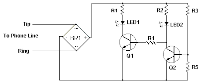
Have you ever been using the modem or fax and someone else picks up the phone, breaking the connection? Well, this simple circuit should put an end to that. It signals that the phone is in use by lighting a red LED. When the phone is not in use, a green LED is lit. It needs no external power and can be connected anywhere on the phone line, even mounted inside the phone.
Phone Busy Indicator Circuit Diagram
Parts:
R1 3.3K 1/4 W Resistor
R2 33K 1/4 W Resistor
R3 56K 1/4 W Resistor
R4 22K 1/4 W Resistor
R5 4.7K 1/4 W Resistor
Q1, Q2 2N3392 NPN Transistor
BR1 1.5 Amp 250 PIV Bridge Rectifier
LED1 Red LED
LED2 Green LED
MISC Wire, Case, Phone Cord
Notes:
Phone Busy Indicator Circuit Diagram
Parts:
R1 3.3K 1/4 W Resistor
R2 33K 1/4 W Resistor
R3 56K 1/4 W Resistor
R4 22K 1/4 W Resistor
R5 4.7K 1/4 W Resistor
Q1, Q2 2N3392 NPN Transistor
BR1 1.5 Amp 250 PIV Bridge Rectifier
LED1 Red LED
LED2 Green LED
MISC Wire, Case, Phone Cord
Notes:
- This is a very simple circuit and is easily made on a perf board and mounted inside the phone.
- LED1 and LED2 flash on and off while the phone is ringing.
- Do not worry about mixing up the Tip and Ring connections.
- The ring voltage on a phone line is anywhere from 90 to 130 volts. Make sure no one calls while you are making the line connections or youll know it.
- In some countries or states you will have to ask the phone company before you connect this to the line. It might even require an inspection.
- If the circuit causes distortion on the phone line, connect a 680 ohm resistor in between one of the incoming line wires and the bridge rectifier.
Tuesday, May 14, 2013
Mobile incoming call indicator

This circuit can be used to escape from the nuissance of obile phone rings when you are at home.This circuit will give a visual indication if placed near a mobile phone even if the ringer is deactivated.
When a call is coming to the mobile phone, the transmitter inside it becomes activated.The frequency of the transmitter is around 900MHz.The coil L1 picks up these oscillations by induction and feds it to the base of Q1.This makes the transistor Q1 activated.Since the Collector of Q1 is connected to the pin 2 of IC1 (NE555) , the IC1 is triggered to make the LED connected at its output pin (pin 3) to blink.The blinking of the LED is the indication of incoming call.
* The coil L1 can be made by making 150 turns of 36 SWG enameled copper wire on a 5mm dia plastic former.Or you can purchase a 10 uH coil from shop if available.
* The circuit can be powered from a 6V battery.
* Assemble the circuit on a good quality PCB.
* C1 & C3 are to be polyester capacitors.
* The electrolytic capacitor C2 must be rated 10V.
Monday, May 13, 2013
Flashing LED Battery status Indicator

Parts:
R1,R7__________220R 1/4W Resistors
R2_____________120K 1/4W Resistor
R3_______________5K6 1/4W Resistor
R4_______________5K 1/2W Trimmer Cermet or Carbon
R5______________33K 1/4W Resistor
R6_____________680K 1/4W Resistor
R8_____________100K 1/4W Resistor
R9_____________180R 1/4W Resistor
C1,C2____________4µ7 25V Electrolytic Capacitors
D1____________BAT46 100V 150mA Schottky-barrier Diode
D2______________LED Red 5mm.
Q1____________BC547 45V 100mA NPN Transistor
Q2____________BC557 45V 100mA PNP Transistor
B1_______________5V to 12V Battery supply
Comments:
LED D1 flashes to attire the users attention, signaling that the circuit is running, so it will not be left on by mistake. The circuit generates about two LED flashes per second, but the mean current drawing will be about 200µA.
Transistors Q1 and Q2 are wired as an uncommon complementary astable multivibrator: both are off 99% of the time, saturating only when the LED illuminates, thus contributing to keep very low current consumption.
The circuit will work with battery supply voltages in the 5 - 12V range and the LED flashing can be stopped at the desired battery voltage (comprised in the 4.8 - 9V value) by adjusting Trimmer R4. This range can be modified by changing R3 and/or R4 value slightly.
When the battery voltage approaches the exhausting value, the LED flashing frequency will fall suddenly to alert the user. Obviously, when the battery voltage has fallen below this value, the LED will remain permanently off.
To keep stable the exhausting voltage value, diode D1 was added to compensate Q1 Base-Emitter junction changes in temperature. The use of a Schottky-barrier device (e.g. BAT46, 1N5819 and the like) for D1 is mandatory: the circuit will not work if a common silicon diode like the 1N4148 is used in its place.
Note:
* Mean current drawing of the circuit can be reduced further on by raising R1, R7 and R9 values.
Sunday, March 24, 2013
Modem Off Indicator
The modem off indicator is intended especially for serious Internet surfers. It will be seen that the circuit of the indicator cannot be much simpler, or there might be nothing left. In spite of its simplicity, it may prove to be a cost-saving device, since it shows at a glance whether the telephone line is free again after the modem has been used. This obviates high telephone charges in case for some reason the modem continues to operate. The circuit depends on the fact that there is a potential of about 40 V on the telephone line when it is not busy. This voltage drops sharply when a telephone call is being made. If, therefore, the circuit is linked to telephone terminals a and b, the lighting of the green LED shows that the line is not busy in error.

Read More..

Subscribe to:
Posts (Atom)