Showing posts with label ignition. Show all posts
Showing posts with label ignition. Show all posts
Thursday, July 11, 2013
Simple Ignition Timer Schematic
This circuit is a tester for flywheel based ignition systems in small aeroplane engines. Basically the same ignition coils are also seen in other small combustion engines used in/on mopeds and lawn mowers in brief, engines without a battery. The part to be tested comprises a primary coil in parallel with the contact breaker. The timing of this contact breaker has to be adjusted correctly.
Since the coil’s primary has a very low resistance it is difficult to determine whether the contact breaker is open or closed. However, you can determine that reliably with this circuit, using an LED and a beeper. The circuit is implemented twice because aviation engines (Cessna, Piper and similar) always have two ignitions in parallel to increase reliability. For two-cylinder engines, well the purpose is obvious.
Ignition Timer Circuit Diagram

The circuit consists of a 555 and a few transistors. The 555 supplies a square wave of about 3000 Hz. This signal goes to power transistors T1 and T2; these can supply quite a bit of power and are robust enough to withstand the voltage transients from the big coils. The test connection (K2 and K3 respectively) are connected in parallel with the contact breaker to be tested, which itself is in parallel with the ignition coil. The frequency of 3000 Hz is either short circuited by the contact breaker or if the points are open is amplified somewhat by the resonance of the coil itself.
This allows you to reliably detect the difference bet ween a closed and open contact breaker, despite the low resistance of the coil, which is in parallel with it. When the contact breaker is open the amplified pulses will turn on T3 and T4 respectively, so that the relevant LEDs turn on and the buzzer will sound.
The components are not critical, but do use a sensitive type for the piezo buzzer. The power supply is 3 V (2 times AA or AAA batteries). Link
This allows you to reliably detect the difference bet ween a closed and open contact breaker, despite the low resistance of the coil, which is in parallel with it. When the contact breaker is open the amplified pulses will turn on T3 and T4 respectively, so that the relevant LEDs turn on and the buzzer will sound.
The components are not critical, but do use a sensitive type for the piezo buzzer. The power supply is 3 V (2 times AA or AAA batteries). Link

Friday, May 31, 2013
Zrx1200 Ignition System Circuit Diagram Wiringcircuit Schematic

Fiat Punto Fuse Diagram 240sx Fuel Pump Wiring Diagram Le2jetronic.

Wiring Diagram Here Free Download Pdf File Source Www.

Basic Thermostat Wiring Diagram.

Can Never Find This Diagram When I Need It So Here It Is This.

Zrx1200 Ignition System Circuit Diagram And Wiring Circuit Schematic.

Wiring Diagram.

Wiring Diagram Electric Mirror Wiring Diagram Peugeot 307 Abs Wiring.

Free Wiring Diagrams Download Free Wiring Schematics.

The Following Schematic Shows A Typical Diagram Schematic Of Polaris.
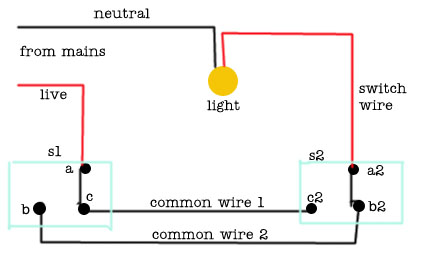
In Pairs Above Is A Simple Schematic Diagram Of How The Wiring For.
Subscribe to:
Posts (Atom)