Showing posts with label panel. Show all posts
Showing posts with label panel. Show all posts
Monday, July 29, 2013
2008 Mercury Sable Passenger Compartment Fuse Panel and Relay Code Diagram
If you found electrical components are not working in a vehicle, a fuse may have blown, so check the appropriate fuses before replacing any electrical component. You can identify the blown fuse by the broken wire within the fuse. The following schematic / diagram shows the location of The 2008 Mercury Sable Passenger Compartment Fuse Panel and Relay. The fuse panel and relay of the 2008 Mercury Sable are located under the instrument panel to the left of the steering wheel.

Always replace the fuse with one that has the specified rating, if the amperage ratings of the replacing fuse is higher, A fuse with higher amperage rating can cause severe wire damage and could start a fire. The table below shows you the exact amperage rating, location and code for each fuse and relay. (fuse number, amperage rating, and circuit protected).
2008 Mercury Sable Passenger Compartment Fuse Panel and Relay Code:
Fuse | Amperage | Description of Circuit Protected |
| 1 2 | 30A 15A | Smart window motor Brake on/off switch, High-mounted brake lamp |
3 | 15A | SDARS, Bluetooth, Family entertainment system (FES)/Rear seat control |
| 4 5 6 7 8 9 10 11 12 13 14 15 16 17 18 19 20 21 22 23 24 25 26 27 28 29 30 31 32 33 34 | 30A 10A 20A 10A 10A 15A 15A 10A 7.5A 5A 10A 10A 15A 20A 20A 25A 15A 15A 15A 15A 20A 10A 10A 20A 5A 5A 5A 10A 10A 10A 5A | Spare SPDJB logic power Turn signals Low beam headlamps (left) Low beam headlamps (right) Interior lights, Cargo lamps Backlighting, Puddle lamps All wheel drive Memory seat/mirror switches, Memory module FEPS module Analog clock Climate control Spare All power lock motor feeds, Decklid release Spare Moon roof OBDII connector Fog lamps Park lamps, License lamps High beam headlamps Horn relay Demand lamps/Interior lamps Instrument panel cluster Adjustable pedal switch Radio, Radio start signal Instrument panel cluster Overdrive cancel switch Compass, Automatic dimming rear view mirror Restraint control module Spare AWD module |
35 | 10A | Steering rotation sensor, FEPS, Rear park assist, Heated seat modules |
| 36 37 38 39 40 41 42 43 44 | 5A 10A 20A 20A 20A 15A 10A 10A 10A | PATS module Climate control Subwoofer (Audiophile radio) Radio Spare Mic mirror, Moon roof, Front lock switches, Radio Spare Spare Spare |
45 | 5A | Relay coils: PDB, Auxiliary A/C, Front and rear wipers, Front blower motor |
46 | 7.5A | Occupant Classification Sensor (OCS), Passenger Airbag Deactivation Indicator (PADI) |
| 47 48 | 30A CB* - | Power windows Delayed accessory relay |
* CB: Circuit Breaker

Thursday, July 11, 2013
Digital Clock with Timer and Solar Panel Regulator
This is a combination digital clock timer and solar panel charge controller used to maintain a deep cycle battery from a solar panel. The timer output is used to control a 12 volt load for a 32 minute time interval each day. Start time is set using 9 dip switches and ends 32 minutes later. The 32 minute duration is set by selecting the 5th bit (2^5 = 32) of a 4040 binary counter (pin 2). The timer also has a manual toggle switch so the load can be manually switched on or off and automatically shuts off after 32 minutes. The time duration can be longer or shorter (8,16,32,64,128,256 minutes etc.) by selecting the appropriate bit of the counter. The timer circuit is shown in the lower schematic just above the regulator.
Basic Clock Circuit diagram
The basic clock circuit (top schematic below) is similar to the binary clock (on another page) and uses 7 ICs to produce the 20 digital bits for 12 hour time, plus AM and PM. A standard watch crystal oscillator (32,768) is used as the time base and is divided down to 1/2 half second by the 4020 binary counter. One half of a 4013 data latch is used to divide the 1/2 second signal by 2 and produce a one second pulse that drives the seconds counter (74HC390 colored purple). The minutes are advanced by decoding 60 seconds (40 + 20) and then resetting the seconds counter to 0 and at the same time advancing the minutes counter. The same procedure is used to advance the hours. The second half of the 4013 latch is used to indicate AM or PM and is toggled by decoding 13 hours and resetting the hours to 0 and then advancing the hours to "one".
Clock Display Circuit diagram
The clock display circuit is shown in the second drawing below and uses 6 more ICs to decode the binary data and drive four seven segment LED displays. The 10s of hours digit is driven with a single 3904 transistor. Two multiplexer circuits (4053) are used to manually select either minutes or seconds for the right two display digits. The two switches shown between the 4053s and below the left 4053 are both part of one DPDT switch which selects either seconds or minutes for the 1X and 10X digits. This switch is shown in the seconds position and the hours digits are blanked with a low signal on pin 4 of the 4511.
The display can also be toggled on and off (totally blank) using a set/reset latch made from a couple 74HC00 NAND gates. A momentary DPDT switch is used to control the latch and toggle the display on or off. The second pole of this switch is used on the upper drawing (connected to the run/stop switch) to set the hours and minutes. Thus this same switch performs both functions of blanking the display and setting the time. The run/stop switch is shown in the normal running mode and supplies a low signal to a NAND gate which prevents accidental setting the time while the clock is running.
Clock Timer Circuit diagram
The run/stop switch also turns on the display (through the diode D2) when in the stop position. The procedure for setting the clock would be to set the (run/stop) switch the stop position and the (seconds/minutes) switch to the minutes position. Then toggle the momentary switch to set minutes and hours of the current time plus one minute. The clock can then be started with the run/stop switch at precisely the right time (+/- 0.5 seconds).
Voltage Regulator (13.6 volts)
The voltage regulator in the lower drawing maintains the battery at 13.6 volts and also supplies the clock and timer circuits with 4.3 volts. The charge LED indicator only comes on when the regulator is supplying max charge to the battery. When the battery voltage reaches 13.6 the regulator reduces the current to whatever is necessary to maintain the voltage and the charge indicator will turn off. The unit I built also included a battery condition indicator (voltmeter using 4 LEDs) to indicate the battery condition so that a failure of the regulator would be indicated by the charge indicator LED turned off and less than 4 LEDs lit on the voltmeter.
Basic Clock Circuit diagram
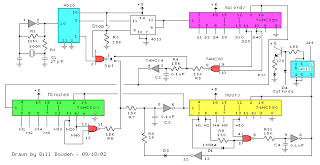 |
The basic clock circuit (top schematic below) is similar to the binary clock (on another page) and uses 7 ICs to produce the 20 digital bits for 12 hour time, plus AM and PM. A standard watch crystal oscillator (32,768) is used as the time base and is divided down to 1/2 half second by the 4020 binary counter. One half of a 4013 data latch is used to divide the 1/2 second signal by 2 and produce a one second pulse that drives the seconds counter (74HC390 colored purple). The minutes are advanced by decoding 60 seconds (40 + 20) and then resetting the seconds counter to 0 and at the same time advancing the minutes counter. The same procedure is used to advance the hours. The second half of the 4013 latch is used to indicate AM or PM and is toggled by decoding 13 hours and resetting the hours to 0 and then advancing the hours to "one".
Clock Display Circuit diagram
 |
The clock display circuit is shown in the second drawing below and uses 6 more ICs to decode the binary data and drive four seven segment LED displays. The 10s of hours digit is driven with a single 3904 transistor. Two multiplexer circuits (4053) are used to manually select either minutes or seconds for the right two display digits. The two switches shown between the 4053s and below the left 4053 are both part of one DPDT switch which selects either seconds or minutes for the 1X and 10X digits. This switch is shown in the seconds position and the hours digits are blanked with a low signal on pin 4 of the 4511.
The display can also be toggled on and off (totally blank) using a set/reset latch made from a couple 74HC00 NAND gates. A momentary DPDT switch is used to control the latch and toggle the display on or off. The second pole of this switch is used on the upper drawing (connected to the run/stop switch) to set the hours and minutes. Thus this same switch performs both functions of blanking the display and setting the time. The run/stop switch is shown in the normal running mode and supplies a low signal to a NAND gate which prevents accidental setting the time while the clock is running.
Clock Timer Circuit diagram
 |
The run/stop switch also turns on the display (through the diode D2) when in the stop position. The procedure for setting the clock would be to set the (run/stop) switch the stop position and the (seconds/minutes) switch to the minutes position. Then toggle the momentary switch to set minutes and hours of the current time plus one minute. The clock can then be started with the run/stop switch at precisely the right time (+/- 0.5 seconds).
Voltage Regulator (13.6 volts)
 |
The voltage regulator in the lower drawing maintains the battery at 13.6 volts and also supplies the clock and timer circuits with 4.3 volts. The charge LED indicator only comes on when the regulator is supplying max charge to the battery. When the battery voltage reaches 13.6 the regulator reduces the current to whatever is necessary to maintain the voltage and the charge indicator will turn off. The unit I built also included a battery condition indicator (voltmeter using 4 LEDs) to indicate the battery condition so that a failure of the regulator would be indicated by the charge indicator LED turned off and less than 4 LEDs lit on the voltmeter.
Saturday, March 30, 2013
Fuse Box Toyota 1996 Corolla Side Kick Panel Diagram
Fuse Box Toyota 1996 Corolla Side Kick Panel Diagram - Here are new post for Fuse Box Toyota 1996 Corolla Side Kick Panel Diagram.


Fuse Panel Layout Diagram Parts: cigar lighter, digital clock display, air conditioning, radio, cassette tape player, tail light, parking lamp, instrument panel light,electric cooling fan, multiport fuel injection, power rear view mirror, stop light, anti lock brake system.
Read More..
Fuse Box Toyota 1996 Corolla Side Kick Panel Diagram


Fuse Panel Layout Diagram Parts: cigar lighter, digital clock display, air conditioning, radio, cassette tape player, tail light, parking lamp, instrument panel light,electric cooling fan, multiport fuel injection, power rear view mirror, stop light, anti lock brake system.
Subscribe to:
Posts (Atom)