Monday, July 8, 2013

Metal Detector Schematic Using CS209A

A very simple metal detector electronic project circuit can be designed using the CS209A integrated circuit manufactured by Cherry Semiconductor.The CS209A integrated circuit is a bipolar monolithic integrated circuit for use in metal detection proximity sensing applications.The CS209A metal detector contains two on-chip current regulators, oscillator and low-level feedback circuitry, peak detection/demodulation circuit, a comparator and two complementary output stages.The oscillator, along with an external LC network, provides controlled oscillations where amplitude is highly dependent on the Q of the LC tank.

Metal Detector Schematic Circuit Diagram


The detector, is a single 100uH coil. The IC has an integral oscillator the choke forms part of an external LC circuit, its inductance being changed by the proximity of metal objects. It is the change in oscillation that is amplified and demodulated. Led 1 will light and the buzzer will sound when the inductance its changed. Set up is easy : R5 is adjusted with the LC away from any metal source so that the LED lights and buzzer sounds. The control is backed off so that the LED goes out and buzzer stops. When the choke comes into contact with any metal object that alters its inductance, LED 1 and the buzzer will activate.

FOr this electronic project youll need the following electronic parts: R1=220ohms, R2,R5=10k,R3=1k ,C1,C3=2.2nF; C2=10uF. Entire circuit can be powered from a 9 volts battery.
Read More..

Sunday, July 7, 2013

Volume Controller Equalizer Using LM1036

This volume controller equalizer electronic project is designed using LM1036 DC tone volume controller with volume and balance circuit for stereo applications .An additional control input of the LM1036 allows loudness compensation to be simply effected.

Volume Controller Equalizer Circuit Using LM1036


The four control inputs of the LM1036 volume controller provides control of the bass, treble, balance and volume functions through application of DC voltages from a remote control system or, alternatively, from four potentiometers which may be biased from a zenner regulated supply provided on the circuit.Each tone response is defined by a single capacitor chosen to give the desired characteristic.
Read More..

Hydrophone Booster Amplifier HA2

Hydrophone Booster Amplifier (HA2)
The HP series Hydrophone Booster Amplifier (HA2) amplifies low-level hydrophone signals over a wide range of frequencies. It has a minimum gain of 25dB and an input and output impedance of 50Ω. The HA2 is designed for use with either Precision Acoustics membrane hydrophone or Precision Acoustics HP Series Hydrophone Measurement System, which is shown in Fig 1.
Hydrophone Booster Amplifier
Alternatively, the HA2 may be used when the acoustic signal is provided by a high output impedance hydrophone, such as a GEC-Marconi membrane device, or a conventional hydrophone. In this instance a BNC/MCX adaptor is used which connects directly to the HP Series Submersible Preamplifier, using it as a buffer amplifier, (i.e. the standard Precision Acoustic HP Series configuration shown in Fig 1 is used, but without the interchangeable probe).
The HA2 amplifier is straightforward to use but the following points should be noted:
  • The output of the amplifier should be correctly terminated in 50Ω before operation.
  • The HA2 amplifier is non-inverting but this is of no consequence when used with the HP Series interchangeable probes as their design takes this into account. However when a submersible preamplifier is used as a high impedance buffer amplifier (as in Fig 2) the system output from the HA2 will be inverted as the HP Series Submersible Preamplifier is inverting.
Before Connecting the unit please read WARNING
To Connect
To  Disconnect
1 Connect Output Load 1 Remove RF Input
2 Apply DC Voltage 2 Remove DC Volts
3 Apply RF Input 3 Remove Load

Specification (HA2 Amplifier Only)
Voltage Gain = 25dB minimum
Bandwidth =  50kHz to 125MHz ±1.0dB
Maximum Output Level = 29dBm for 1dB compression (18.1V pk – pk into 50Ω load)
Input Impedance = Nominal 50Ω
Output Impedance  Nominal 50Ω (VSWR 2:1)
Output Noise Level = Typically 70μV pk – pk (bandwidth 125MHz)
Noise Figure = Typically 10dB
Phase = Non-inverting
Terminations:
Front panel = Input BNC socket BNC Output socket
Rear panel Power Requirements = 28v dc output to supply DC Coupler 100/120/220/240V ac, 50 to 60Hz,
7.5W
Operating Temperature = 0 to 50°C
Size = (90mm × 205mm ×194mm)
Weight = 2.6kg


Streampowers
Read More..

Off Hook Telephone Line Indicator

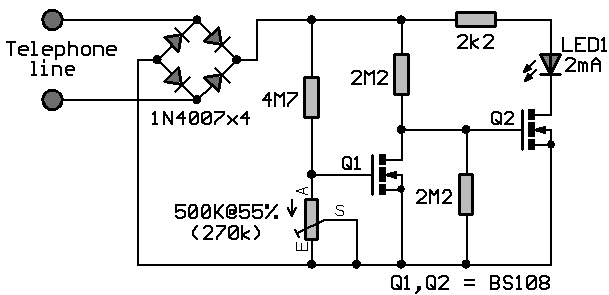
The circuit is designed to connect in parallel with the telephone line, to monitor and detect if any telephone in the same line is busy, with the indication of the LED and which is self-powered so that it does not provide any load on a telephone line.

Light Emitting Diode (LED) – a semiconductor diode that is commonly a source of light when electric current pass through it Metal Oxide Semiconductor Field Effect Transistor (MOSFET) – a device utilized for switching and amplification of signals BS108 – a 250 mA and 200 Volts small signal MOSFET designed for high voltage, high speed switching applications such as relay drivers, CMOS logic, line drivers, TTL or microprocessor to high voltage interface and high voltage display drivers Diode Bridge – also known as bridge rectifier which has four diodes arranged in a bridge configuration where the output voltage has the same polarity with either polarity of the input voltage 1N4007 – a general purpose plastic rectifier with reverse voltage from 50 Volts to 1000 Volts and forward current of 1.0 Ampere

When none of the telephone lines is in use or on-hook, the voltage across the line is around 48V. In this state, the gate of transistor Q2 is shorted to its source during the conduction of Q1. This causes the LED to be disabled while Q2 is turned OFF. When one telephone extension along the telephone line changes to off-hook or in use condition, a voltage drop from 5V to 15V is detected. This will in turn cause Q1 to turn OFF because of the very low voltage across the gate of Q1 which is equal to 6% of the line voltage. Transistor Q2 then will be biased at around half of the line voltage.

Off-Hook Telephone Line Indicator Circuit Diagram


Off-Hook Telephone Line Indicator

 The sudden line drop of voltage triggers Q2 to light up the LED that will give a sign that the line is in use. Using the same line, the circuit is unseen with other telephone devices. A current-limiting resistor is used to maintain the low current of LED1 while the local telephone line parameters dictate the variation of other component’s values. The power of the circuit is provided by the telephone line. Other voltage protection may be used with some reliable design in addition to the current-limiting resistor. This is important to avoid any grounding effects from conducting surfaces within the circuit.

To ensure that transistor Q1 is fully biased while the line is free or not in use where LED1 is OFF, a 500K ohm MOSFET trimmer is used for the desired adjustment. A MOSFET is a three-terminal semiconductor component with a conducting channel in its output and a built-in capacitor at its input. To increase the values of any of the two resistors connected to the gate of Q2, a 200V MOSFET can be used in the place of Q2 if BS108 is not available. However, plain transistors like the bipolar junction can be used but with lower values to allow greater currents to pass through the line that is not in use. The bridge rectifier comprising of four 1N4007 diodes are performing the conversion of AC input into DC output.

MOSFET can function in two ways. The first is known as depletion mode wherein the channel shows its maximum conductance in the absence of a voltage on the gate. The second way that the MOSFET can function is known as enhancement mode wherein the device is not conducting even in the absence of a voltage on the gate because no channel is produced. A channel is being created with the application of a voltage to the gate. To generate better conductivity, greater voltage to the gate is required.

MOSFET drivers are applied in electronic motor control for different types of motors. Also, they are specifically used with long duty cycles, high operating frequency above 200 KHZ, lower output power, and wide load variations. The largest application of MOSFETs are the switched mode power supplies and in battery charging applications. In transducer drivers for high power devices such as light bulbs and motors, large current output with a small input is provided by MOSFETs. Since they are more non-linear than BJTs while producing less distortion, they can be utilized with Hi-Fi amplifiers. In constructing integrated circuits, MOSFETs are very useful since they can be made very compact. Although MOSFETs can get damaged by static electricity at higher voltages, they still provide several advantages as compared to other transistors which include faster switching time than BJT, lower losses than BJT, very small switching current, and least effects of temperature.

This telephone line indicator does not only tell when a telephone line is in use if a plurality of telephones are all setup to the same telephone line, but also prevents interruptions during personal calls. Additionally, it can also help to prevent costly and unwanted disruption of modem calls and fax, it alerts a person when a call is done and the phone is free to use, and the LED light indicates the line is in use.

To avoid any injury, it is a prerequisite to take extra precautionary measures when connecting any circuit to the telephone lines, which can produce life-threatening voltages during normal operation. During a lightning storm, it is better to keep distance from telephone lines.. Legal aspects are imposed in different countries for connecting things to telephone lines. The circuit should be better built with a plug-in cord for easy removal in case of fault occurrences. Otherwise, it would be best to consult a licensed telephone operator.
Read More..

18 LED Dimmable LED Lamp

This circuit is a dimmable white LED lamp array with 18 LEDs. The lamp brightness is regulated as long as the input voltage is above 10.5V. A low-dropout analog voltage regulator is used for a simple and relatively efficient design. The lamp produces enough light to use as a a reading lamp or a small work lamp. 

Project Image


18 LED Dimmable LED Lamp

Specifications:
  • Power Requirements
  • Input Voltage: 10.5-16V DC
  • Input Current: 11-150mA at 12VDC
Theory:
The 12V DC input voltage is routed through the 1A fuse and the on/off switch. The 1N4001 diode acts as a crowbar device. If reverse polarity is applied, the fuse will blow and the rest of the circuitry will be protected. Power is sent to the LM2941CT voltage regulator IC. The regulator is wired to produce a voltage range from 5.5V (dim) to 8.3V (bright).

18 LED Dimmable LED Lamp Circuit Diagram

18 LED Dimmable LED Lamp

The 4.7K resistor across the 1K brightness adjustment potentiometer produces a non-linear brightness adjustment to compensate for the eyes logarithmic brightness perception response. The LEDs are organized in six series groups of three with a 24 ohm current limiting resistor on each group. This arrangement limits the maximum current through each LED group to around 20mA.

Use:
Connect the DC input terminals to a 12V source, such as a 12V lead acid battery. Be sure to observe the correct polarity. Turn the power switch on and adjust the brightness adjustment for the desired brightness.

Parts:
    1X LM2941CT low-dropout voltage regulator
    1X aluminum heat sink
    1X 1A DC rated fuse
    1X DC switch
    1X 1N4001 diode
    2X 1K 1/4W resistors
    2X 4.7K 1/4W resistors
    6X 24 ohm 1/4W resistors
    1X 1K linear potentiometer
    18X 5mm white LEDs, 20mA max
    1X 22uF 16V electrolytic capacitor
    1X 100nF 25V monoblock capacitor
 
Read More..

Saturday, July 6, 2013

IR Remote Control Tester

 Notes:
As I was developing my IR Extender Circuit, I needed to find a way of measuring the relative intensities of different Infra red light sources. This circuit is the result of my research. I have used a photodiode, SFH2030 as an infra red sensor. A MOSFET opamp, CA3140 is used in the differential mode to amplify the pulses of current from the photodiode. LED1 is an ordinary coloured led which will light when IR radiation is being received. The output of the opamp, pin 6 may be connected to a multimeter set to read DC volts. Infra red remote control strengths can be compared by the meter reading, the higher the reading, the stronger the infra red light. I aimed different remote control at the sensor from about 1 meter away when comparing results. For every microamp of current through the photodiode, about 1 volt is produced at the output. A 741 or LF351 will not work in this circuit.  Although I have used a 12 volt power supply, a 9 volt battery will also work here.
Read More..

Stepper Motor Controller Using the NJM3771

An very simple stepper motor driver circuit can be designed using the NJM3771 stepper motor driver integrated circuit designed by New Japan Radio Co. Ltd. This stepper motor driver electronic project is very simple to design and require few external components . 

Stepper Motor Controller Circuit diagram


The NJM3771 IC is especially developed for use in microstepping applications in conjunction with the matching dual DAC (Digital-to-Analog Converter) NJU39610. The NJM3771 contains a clock oscillator, which is common for both driver channels; a set of comparators and flip-flops implementing the switching control; and two H-bridges with internal recirculation diodes. Also this stepper motor driver project supports a wide range input voltage : +5 V is required for logic and +10 to +45 V for the motor powering . The maximum output current that is supported by this circuit is around 650 mA per channel. The NJM3771 stepper motor driver has an selectable slow fast current decay for improved high speed Microstepping .

The output current to the motor winding is mainly determined by the voltage at the reference input and the value of the sensing resistor, RS. The voltage across the sensing resistor is fed back to the comparator via a low-pass filter section, to prevent erroneous switching due to switching transients ( the recommended filter component values, 1 kohm and 820 pF). This driver IC is designed for bipolar motors, i.e., motors that have only one winding per phase but unipolar motor, having windings with a center tap, can also be used .
Read More..