Friday, August 30, 2013
Pressed Button Sound Indicator
sing this electronic scheme can be made an electronic circuit that allows a sound indication for a button.The circuit is based on a 7555 integrated timer (CMOS version of the well-known ment 555) is connected as a multivibrator astabil .His output is a rectangular pulse with a frequency of 700 Hz, which is used to control a small buzzer.
Pressed Button Sound Indicator Schematic

Pressed Button Sound Indicator Schematic
The circuit will oscillate be prevented if pin 4 of integrated circuit is connected to 0 V.
Friday, August 16, 2013
Type of pneumatic valve
Pneumatic Valve Types
Pneumatic valves have many types and functions. pneumatic valves .The role as a regulator / controller in the pneumatic system. Components such control or so-called valves (Valves). Pneumatic Valve types can be grouped according to the construction design as follows:

a. Poppet valves (Poppet Valve Pneumatic)
■ Ball Valve (Ball Valve Pneumatic Seat)■ Disc Valves (Pneumatic Valve Seat Disc)
b. Slide valve (slide valve Pneumatic)
■ Longitudinal Slide
■ Slide Plate
Meanwhile, according to its function valves are grouped as follows:
a) Valves Steering (Directional Control Valves)
b) One-way Valve (Non Return Valves)
c) Regulatory Pressure Valve (Pressure Control Valves)
d) Flow Control Valves (Flow Control Valves)
e) open-close valve (Shut-off valves)
While the arrangement order in the pneumatic system can be described as follows:
■ The input signal or input element gets energy directly from
power source (air felts) are then transmitted to the processor
signal.
■ The signal processor or processing element signal processing
logic inputs are to be forwarded to the fi nal control element.
■ end of the control signal (final control element) that will drive the direction of movement of the actuator output (working element) and this is the end result of the pneumatic system.
- Pneumatic-Valve Types
Wednesday, August 14, 2013
New LG OLED Display
OLED display technology also known as organic semiconductors,which is considered to take over LCD and plasma technology, the next-generation flat panel display technology, which has colorful, dynamic clarity, slim size and lower power consumption. It has been in mobile phones more widely used.
However, before the announcement of LG, Samsung Electronics is also from South Korea said it will be on display CES 55?? LED TV at next year. Therefore, this behavior is also considered to be forced to move LG deal with Samsung.
PS, if you are looking for the cases for consumer electronics.
Monday, August 12, 2013
Simple Programmable Attenuator Circuit
This Simple Programmable Attenuator Circuit performs the function of dividing the input signal by a selected constant (1, 2, 4, 8, etc.). While T, Z, or L sections could be used in the input attenuator, this is not necessary since the amplifier loading is negligible and a constant input impedance is maintained. The circuit is thus much simpler and more accurate than the usual method of constructing a constant impedance ladder, and switching sections in and out with analog switches. Two identical circuits can be used to attenuate a balanced line .
Simple Programmable Attenuator Circuit

Saturday, August 10, 2013
DC Coupled Current Monitor Circuit
This is design circuit for DC coupled current monitor that is eliminates the previous circuit’s trim but pulls more current from the APD bias supply. A1 floats powered by the APD bias rail. This is the figure of the circuit.

The 15V zener diode and current source Q2 ensure A1 never is exposed to destructive voltages. The 1kW current shunt’s voltage drop sets A1’s positive input potential. A1 balances its inputs by feedback controlling its negative input via Q1. As such, Q1’s source voltage equals A1’s positive input voltage and its drain current sets the voltage across its source resistor. Q1’s drain current produces a voltage drop across the ground referred 1k resistor identical to the drop across the 1kW current shunt and, hence, APD current. This relationship holds across the 20V to 90V APD bias voltage range. The 5.6V zener assures A1’s inputs are always within their common mode operating range and the 10M resistor maintains adequate zener current when APD current is at very low levels.
Two output options are shown. A2, a chopper stabilized amplifier, provides an analog output. Its output is able to swing to (and below) zero because its V– pin is supplied with a negative voltage. This potential is generated by using A2’s internal clock to activate a charge pump which, in turn, biases A2’s V– pin. A second output option substitutes an A-to-D converter, providing a serial format digital output. No V– supply is required, as the LTC2400 A-to-D will convert inputs to (and slightly below) zero volts. [Schematic’s circuit source: Linear Technology Notes].
Thursday, August 8, 2013
Switchmaking Proper Connection

Com Wp Content Uploads 2008 01 2 Way Switch Wiring Diagram Jpg.

Installing An Additional Light Point 2 Gang Switch.
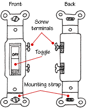
Types Of Light Switches Hometips.

Wiring Diagram Light Switch Wiring Diagram Light Switch 34038.

Diagram 2 The Wiring Is Very Similar To Diagram 1 Except A Switch Has.

Light Switch Wiring Diagram Uk Reviews And Photos.

Read Switch This Wiring Which Controls Light Switch Is There.

Three Way Switch Making The Proper Connection.
Two Way Light Switch Wiring.

Wiring A Double Light Switch Diagram Electrical Information Blog.
Tuesday, August 6, 2013
Wiring Harness Cable Connection Diagram Sourcemanual

Posts Datsun 510 Wiring Diagram And Cable Harness Schematic 2004.

Wiring Harness And Cable Connection Diagram Here Source Manual.

Wiring Harness Connectors Wiring Harness Connectors Manufacturer.

Hid Xenon Bulb D2s D2r D2c Wiring Harness Socket Adapters 2080.

Chevy Truck Underhood Wiring Diagrams Chuck S Chevy Truck Pages Com.

Engine Wiring Diagram 4 Automotive Wire Harness Prestolite Wire.

Cassette Cd And 6 Speakers Audio System Wiring Circuit Schematic.
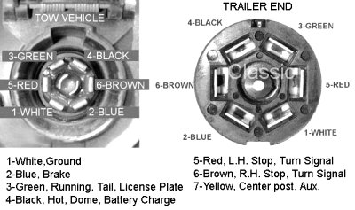
Troubleshooting Trailer Wiring.

Typical 7 Way Trailer Wiring Diagram Circuit Schematic.
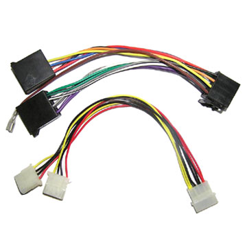
Wiring Harness Wiring Harness.
Sunday, August 4, 2013
12V Halogen Lamp Electronics Transformer Circuit Diagram
The following file is an application note from ST.com containing description of the 12V Halogen Lamp Electronics Transformer Circuit Diagram. These lamps are available with voltage ratings of 6, 12 or 24 Volts, and so a transformer is needed in order to provide the lamp with a low voltage supply from either 110V a.c. or 220V a.c. mains.
The topology of the circuit is the classic half-bridge. The line voltage is rectified by the full-bridge rectifier, generating a semi-sinusoidal voltage at double the line frequency.
Get more information regarding the 12V Halogen Lamp Electronics Transformer Circuit Diagram design here.
Subscribe to:
Posts (Atom)