Wednesday, June 12, 2013
STK465 Stereo Power Amplifier circuit
STK465 - 30 watt Stereo Power Amplifier


The STK465 Amplifier circuit is stereo and has two channels of amplifier in a nutshell. It is a formal designing that develops positively all the particularities completing. The amplifier can be supplied from a line of double polarity. Still it can function under a wide region of tendencies (±10V as ±28V). The requirements of current depend from the force of expense and it can they begin from 120mA up to 1A. It is very important the catering to be sufficiently unharnessing, so that is avoided imports of annoying noises.
Read More..
STK465 - 30 watt Stereo Power Amplifier
Source: http://sharingmanual.blogspot.com/2012/08/stk465-30-watt-stereo-power-amplifier.html
Completed STK465 is an amplifier of acoustic frequencies that offers qualitative output, using minimal exterior elements. Substantially he is one of big completed force. When it functions with tendency 56V then the tendency will be ± 28V as for the ground. With this recommended tendency of catering, the attributed force is 30 WRMS in charge 8 Ohm.Source: http://sharingmanual.blogspot.com/2012/08/stk465-30-watt-stereo-power-amplifier.html
The STK465 Amplifier circuit is stereo and has two channels of amplifier in a nutshell. It is a formal designing that develops positively all the particularities completing. The amplifier can be supplied from a line of double polarity. Still it can function under a wide region of tendencies (±10V as ±28V). The requirements of current depend from the force of expense and it can they begin from 120mA up to 1A. It is very important the catering to be sufficiently unharnessing, so that is avoided imports of annoying noises.
Electronics Circuit Application
Remote Control circuits For Home Appliances
Here is the circuit diagram of Remote Operated Home Appliances or Remote controlled Home appliances. Connect this circuit to any of your home appliances (lamp, fan, radio, etc) to make the appliance turn on/off from a TV, VCD, VCR, Air Conditioner or DVD remote control. The circuit can be activated from up to 10 meters. It is very easy to build and can be assembled on a veroboard or a general-purpose PCB.
Parts:
R1 = 220K
R2 = 330R
R3 = 1K
R4 = 330R
R5 = 47R
C1 = 100uF-16V
C2 = 100nF-63V
C3 = 470uF-16V
D1 = 1N4007
D2 = Red LED
D3 = Green LED
Q1 = BC558
Q2 = BC548
IR = TSOP1738
IC1 = CD4017
RL1 = Relay 5V DC
The 38kHz infrared rays generated by the remote control are received by IR receiver module TSOP1738 of the circuit. Pin 1 of TSOP1738 is connected to ground, pin 2 is connected to the power supply through R5 and the output is taken from pin 3. The output signal is amplified by Q1. The amplified signal is fed to clock pin 14 of decade counter IC CD4017 (IC1). Pin 8 of IC1 is grounded, pin 16 is connected to vcc and pin 3 is connected to D2 (Red LED), which glows to indicate that the appliance is ‘off.’
The output of IC1 is taken from its pin 2. D3 connected to pin 2 is used to indicate the ‘on’ state of the appliance. Q2 connected to pin 2 of IC1 drives relay RL1. D1 acts as a freewheeling diode. The appliance to be controlled is connected between the pole of the relay and neutral terminal of mains. It gets connected to live terminal of AC mains via normally opened (N/O) contact when the relay energizes. If you want to operate a DC 12 volt relay then use a regulated DC 12 volt power supply for DC 12 volt Relay and remember that the circuit voltage not be exceeded more than DC 5 volts.
Remote Control circuits For Home Appliances
.
The Upcoming Iphone Car Kit A Good Travel Partner To Drive
The standby capacity deficiencies and not charge in the car When you are enjoying the beauty of nature, is not bothering you by this embarrassment? You can not enjoy your favorite music on the road; When you are speeding on the highway, you can answer a important phone. Do you have encountered? Now the good new is coming.
The recent series against the iPhone and the iPod launched Six-vehicle equipment - aiPower CA601. Adjustable elastic support products, which support 90-degree rotation, to provide users with a variety of operation, standard USB output interface can not only charge for a variety of digital devices, car audio system can also realize the iPhone hands-free calls, the other , aiPower CA601 can also be iPhone and the iPods music through the FM transmitter to car stereo channels to play.
Many MP3 users to buy the car kit in order to enjoy music anytime, anywhere to bring the fun, aiPower CA601 taking into account the MP3 car kit, users can iPhone and iPod products within the audio file through the FM transmitter to car stereo playback channels This feature is not only practical, but also to restore the high-quality sound, giving the user unprecedented comfort.
And other commercial car kit is different, aiPower CA601 can adjust the angle of the stent, the fixed phone can support one end of the bracket rotated 90 degrees to meet the habits of different users, while for most users get used to the current iPhone Case issues, the Patriots designers have done in research and development CA601 sufficient time to consider the design of the stent, aiPower CA601 using a flexible design that allows the iPhone to any equipment, protective cover products easily into the holder, and ensure stable and firm.
I believe this aiPower CA601 will be your best travel companion.
Read More..
The recent series against the iPhone and the iPod launched Six-vehicle equipment - aiPower CA601. Adjustable elastic support products, which support 90-degree rotation, to provide users with a variety of operation, standard USB output interface can not only charge for a variety of digital devices, car audio system can also realize the iPhone hands-free calls, the other , aiPower CA601 can also be iPhone and the iPods music through the FM transmitter to car stereo channels to play.
Many MP3 users to buy the car kit in order to enjoy music anytime, anywhere to bring the fun, aiPower CA601 taking into account the MP3 car kit, users can iPhone and iPod products within the audio file through the FM transmitter to car stereo playback channels This feature is not only practical, but also to restore the high-quality sound, giving the user unprecedented comfort.
And other commercial car kit is different, aiPower CA601 can adjust the angle of the stent, the fixed phone can support one end of the bracket rotated 90 degrees to meet the habits of different users, while for most users get used to the current iPhone Case issues, the Patriots designers have done in research and development CA601 sufficient time to consider the design of the stent, aiPower CA601 using a flexible design that allows the iPhone to any equipment, protective cover products easily into the holder, and ensure stable and firm.
I believe this aiPower CA601 will be your best travel companion.
Wednesday, June 5, 2013
Wiring Panelstructured Home Wiring
Cat 5 Wiring.

Comparison Between Cat5 Cat5e Cat6 Cat7 Cables.
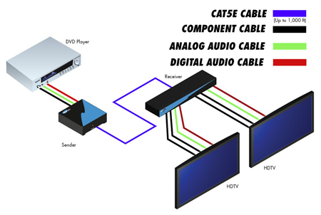
Gefen Component Audio Over Cat5 Wiring Diagram.
Cat5 And Cat6 Wiring Diagrams I Use Cat5 B Some People Use Cat5.

Cat5 Network And Computer Cables Patch Cables Cat5 Cat5e Cables And.

Ethernet Cable Wiring Diagram Straight Lg.

Wiring Panel Structured Home Wiring.

Usb To Cat5 Adapter 6wirepatch Gif.

Make Networks Ethernet Cable Configuration.

Cat5 Wiring.
Honda Cb750 Sohc Engine Diagram Wiring Diagrams

Honda Cb750 Sohc Engine Diagram Car Wiring Diagrams.

Diagram Electrical Circuit Diagram Related Posts Wiring And Connectors.

Relay Wiring.

Volvo S60 S60r S80 Car Wiring Diagram 2005 Circuit Schematic.

2001 Audi B5 Radio System Schematic Diagram It Consists Of.

Wiring Diagram Here Free Download Pdf File From Jeep Justanswer.

1997 Geo Metro Wiring Diagram Car Wiring Diagrams Auto Addicts.

Tda1562q Car Audio Amplifier Schematic.

Wiring Com Home Of The Original Color Laminated Car Wiring Diagram.

Wiring Diagram Audio Wiring Diagrams For Jeep Cherokee Laredo Audio.
Circuit Diagram

Wall Receptacle I Am Currently Replacing A Light Switch With A Ceiling.

Wiring Diagram The Manual Is Divided Into Following Sections Wiring.

Wiring Diagram Outdoor Light Switch Pictures.

How To Wire A Light Switch Life123.

Volkswagen Beetle Wiring Diagram Electrical Schematics Cable Routing.

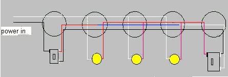
Line Diagram Of A Two Way Lighting Circuit Using Junction Boxes Fig 1.
Way Circuit Diagram.
Two Light Runs Between 3 Way Switches Electrical Wiring Forum.

Home Control Fundamentals Wiring A 3 Way Wall Switch.

Light Switch 3 Way Wiring.
Tuesday, June 4, 2013
Stereos Subwoofer Wiring 2ohm

Subwoofer Wiring Diagrams Understand Ohms Law.
Car Audio Questions Page 4 The Best Forum Ever General.

How To Additional Subwoofer System Wiring Connection For Vw Golf Iv.
Ideally The Power Capacitor Should Be As Close As Possible.

Triple Subwoofer Systems.

Choosing Subwoofer Wiring For Your Passive And Powered Subwoofer Box.

Car Stereos Amp And Subwoofer Wiring 4 Ohm Dvc Sub Or 2ohm Dvc Sub.

Subwoofer Wiring Diagrams Two 2 Ohm Dual Voice Coil Dvc Speakers.

Wiring A Sub To Pre Existing Amp Speakers Honda Tech.

Wiring Two Dual Voice Coil Subs To One Mono Amp Page 2.
Fuse Box Diagram Mercedes 190 E 2.3 1998


Fuse Panel Layout Diagram Parts: combination relay, anti theft alarm,
turn/hazard signal, heated rear window wiper motor, power window relay,
washer relay, intake manifold, pre heater, power seat relay, auxiliary
fuse, power seat, headlamp.
Ceiling Components

An Old Wiring Diagram There Are Two Red Wires Coming From The Fan.

Ceiling Fan Wiring Interior And Exterior Design.

Ceiling Fan Installation Wiring Pictures.

Ceiling Light Wiring Diagram Group Picture Image By Tag.

Harbor Breeze Ceiling Fan Wiring Instructions Ehow Com.
Installing The Mounting Bracket For The Ceiling Fan.

Ceiling Fan Installation Instructions Signature Lighting And Fans.

Ceiling Fan Components.

Ceiling Fan Installation Instructions Red Wire Images.
Royalty Free Stock Photo Wiring Ceiling Fan Image 1286835.
Subscribe to:
Posts (Atom)